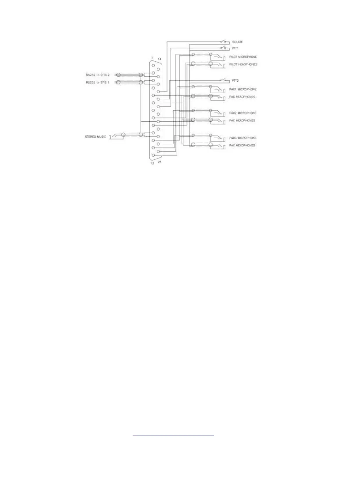
This diagram shows a more complex four place installation in a '1+3'
configuration including 'Pilot Isolate', a stereo music input and remote control
by two EFISs. Note the shielded cables used for the RS232 connections to
each EFIS and that the shields for those cables are only connected at one
end.
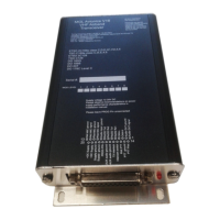
Transceiver installation
A minimum installation requires the following:
●
Power supply (typically 12VDC or 24VDC)
●
Pilot headset - microphone and headphones
●
Pilot PTT switch
●
Antenna tuned to the VHF airband connected via RG400 or equivalent
50 ohm coaxial cable
These optional items may be connected:
●
Up to three additional separate headsets
●
One additional PTT switch
●
Stereo music source
●
One or two auxiliary audio sources
●
One or two RS232 connections to EFIS systems (if used)
For more information visit
www.MGLAvionics.co.za
25