Optidew User’s Manual
10 97551 Issue 1, February 2018
INSTALLATION
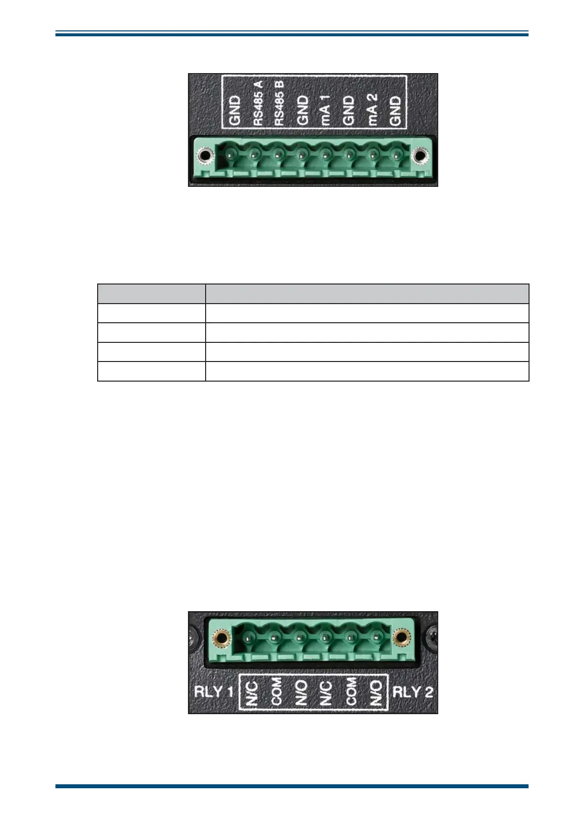
2.3.2.2 Current Outputs
Figure 11
Analog output connector
The rightmost four of the pins on this connector are used for mA outputs.
See section 3.2 for information on configuring the analog outputs
Pin Label Description
mA1 Channel 1 Current Output
GND Channel 1 Ground
mA2 Channel 2 Current Output
GND Channel 2 Ground
2.3.2.3 Relay Contacts
There are two sets of relay contacts available via the output connector:
Process Alarm (Relay 1)
This relay changes state to indicate that the process variable has exceeded the alarm
set point value. See section 3.2 for details on how to configure the process alarm trip
criteria. This alarm can also be used to give an early indication that the Optics require
cleaning.
System Alarm (Relay 2)
This relay changes state to indicate a fault has occurred which requires operator
intervention. See section 4.6 for detailed information on faults.
Figure 12
Relay contact connector