Optidew User’s Manual
12 97551 Issue 1, February 2018
INSTALLATION
2.4 Sensor Installation
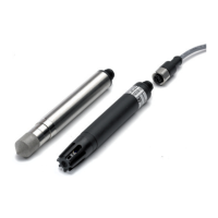
The dew-point sensor contains the optical system and the chilled mirror. It is fitted with
a 12-pin M12 connector to allow easy and secure connection to the instrument using
the supplied sensor cable.
The available options for sensor installation are:
• via a permanently installed sample port into which the remote sensor can
be inserted or
• via a sensor block immediately attached to the sensor around which the
sample circulates or
• in an ambient environment where the sample is diffusing through the
sensor.
NOTE: Ensure that the mirror surface is cleaned before installation. See
Section 5 (Maintenance) for cleaning details.
Connect the remote sensor cable to the sensor and to the instrument via the connector
on the rear panel. The connector is a standard M12. Align the locating pin with the slot
on the socket and press the connector into place. Rotate the outer collar of the cable-
mounted part in a clockwise direction until finger tight.
If exchanging the sensor, refer to section 5.2.
2.4.1 Environmental monitoring
If the instrument is to monitor the conditions in an environment, the sensor must be
located in a representative position, i.e. not under an air conditioning vent.
A sensor wall mounting bracket is available to conveniently secure the sensor to a wall
or panel.
NOTE: It is recommended that the sensor is fitted with the porous aluminium
guard to baffle it from flowing air currents.
2.4.2 Sample flow monitoring
If the sensor is installed within a sealed gas system it must be fixed securely without any
possibility of leaks. Ensure that the sample flow across the sensor is correctly regulated.
The gas connections for the remote sensor are either via a permanently installed sample
port into which the remote sensor can be inserted or via a sensor block immediately
attached to the sensor around which the sample circulates. Gas sample entry into the
sensor block is via couplings that can be installed into the provided ⅛” NPT female
threads. A bonded seal is provided to fill the connection between the sensor and the
block.
Ensure that all connections to and from the sensor block are made with appropriate
materials and fittings for moisture measurement. For guidance on suitable apparatus,
see section 4.3.