MICOM-3F/3T/3R HF-SSB Owner’s Guide
114
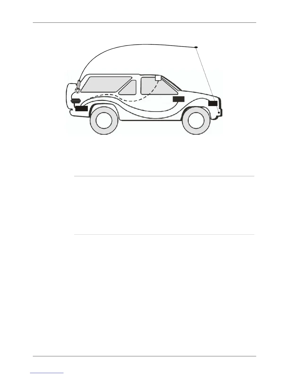
Figure 16 shows the location of the installed components within the vehicle.
ATU
DC Power Cable
BAT
Control
Head
RadioRadio
1
2
Control Head
Cable
Figure 16. Typical MICOM-3T Installation Within Vehicle
The MICOM-3T model requires the connection of two cables across the length of the vehicle because
the radio transceiver is located in the trunk. If the battery is located in the rear section of the vehicle,
the power cable extends to the battery location.
Notes
1. The upper installation (number 1 in Figure 16), is recommended over the front
installation (number 2 in Figure 16) because of the covering that protects the
control head from direct sunlight.
2. To achieve maximum operating range, the antenna should be mounted as high
on the vehicle body as possible without striking overhead obstructions in the
normal service area of the vehicle. Select a mounting location on a flat portion
of the vehicle body, compatible with the maximum allowable high voltage
lead-in cable length.