MICOM-3F/3T/3R HF-SSB Owner’s Guide
120
Connectors
MICOM-3F/3T Microphone Connector
The microphone connector is located on the lower part of the radio front panel. Table 3 lists the
functions of the microphone connector pins.
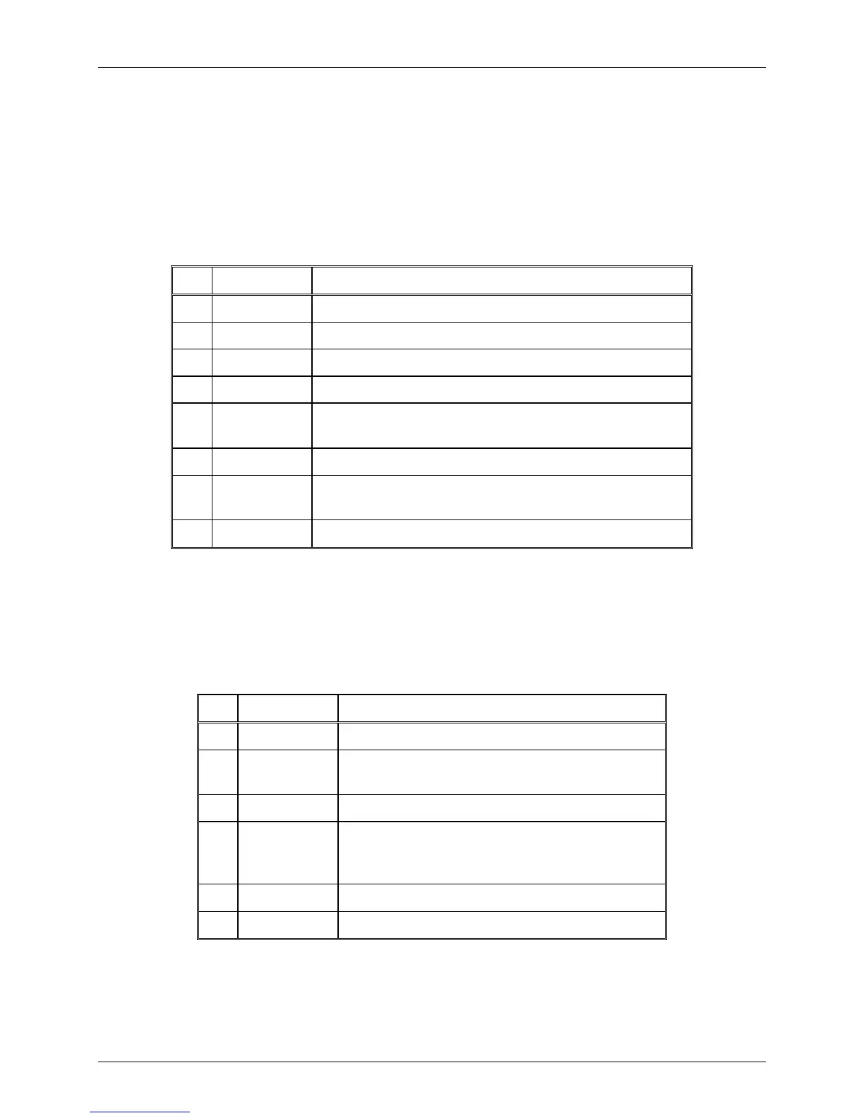
Table 3. MICOM-3F/3T Microphone Connector, Pin Functions
Pin Designation Description
1 SWA+ Power output to the microphone
2 RXD Serial communication line (input)
3 TXD Serial communication line (output)
4 GND Ground line
5 MIC AUDIO
Input audio signals generated by the microphone (600 Ω
impedance; 100 mV tone is required for full output power).
6 PTT MIC Activates transmission by short to ground.
7 MONITOR Mutes the speaker before transmission is enabled (short
momentary to ground to open speaker).
8 AUDIO OUT
Receive audio output to earphone (600 Ω, 300 mVRMS)
MICOM-3R Audio Connectors
The audio connectors are located on the lower left part of the radio front panel. An external speaker
and handset can be plugged into both connectors. Table 4 lists the functions of the audio connector
pins.
Table 4. MICOM-3R Audio Connectors, Pin Functions
Pin Designation Description
A GND Ground line
B HANDSET
AUDIO
Receive audio output to external speaker
C PTT MIC Activates transmission by short to ground
D MIC AUDIO Input audio signals generated by the microphone
(600 Ω impedance; 6 mV tone is required for full
output power)
E AUDIO OUT
Receive audio output (600 Ω) to earphone
F SWA+ Power output to microphone