MICOM-3F/3T/3R HF-SSB Owner’s Guide
116
Step 2.
Thread the ends of the red and green wires from the power connector through the
two fuse holder caps. Cut apart the two fuse clips and solder or crimp them to the
wires.
Step 3.
Install the 30-A fuse in the fuse holder on the red wire, and the 7.5 A fuse in the fuse
holder on the green wire. Then assemble the fuse holders.
Step 4.
Crimp or solder the supplied lugs to the red, green, and black wires.
Step 5.
Connect the lugs on the red and green cables together to the positive terminal of the
battery. Then connect the lug on the black wire to the negative terminal of the
battery.
Notes
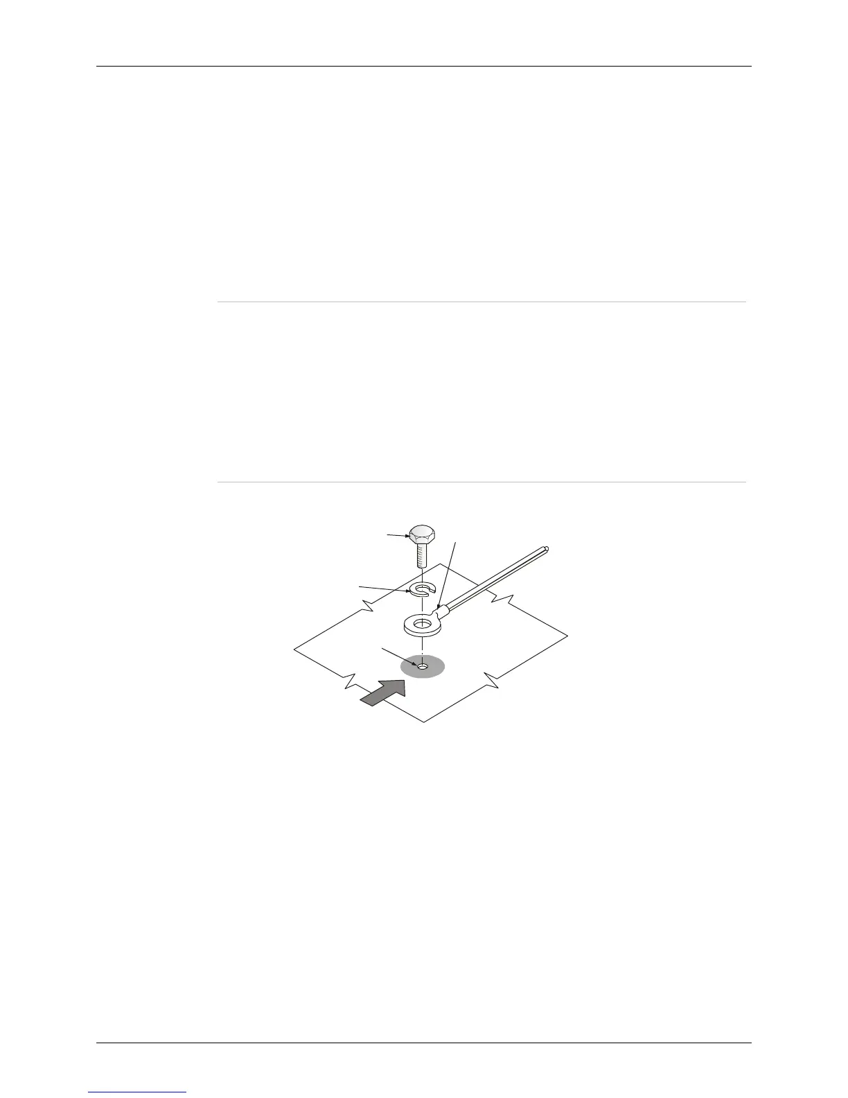
1. It is recommended to attach the black (ground) wire to the vehicle’s chassis.
The point of attachment should be located as close as possible to the radio.
Refer to Figure 19.
2. In front installation, add one ferrite (supplied with the installation radio kit) on
the DC cable as close as possible to the radio.
3. In trunk mount installation, add one ferrite (supplied with the installation radio
kit) on the DC cable as close as possible to the radio and one ferrite on the
control cable between the control head and the radio.
1/4” Lockwasher
Throughly
Clean this Area
Chassis Cable
and Lug
Floor Surface
No 14x3/4"
Self-Tapping
Screw
3/16' (187")
Diameter Hole
Figure 19. Wire Attachment to Chassis