10
PLEASE NOTE: If you have purchased a Trak-Star speed
sensor, disregard the section on magnetic speed sensors
and install the Trak-Star as described in the instructions
packed with the unit.
Locations where the sensor may be installed:
1. Non-driven wheel on tractor, vehicle or implement. This
is less susceptible to errors resulting from wheel slip.
2. Tractor, vehicle or planter drive shaft. This type of
mounting is recommended for trucks, four-wheel drive
tractors or other equipment that has poor or no access
to a non-driven wheel.
Installation (cont)
Speed Sensor Installation
Locate the Following Parts:
• Speed Sensor Cable
• Mounting “L” Bracket
• Magnet Clips
• Magnets
• Cable Ties
Magnets
Please read the following information about magnet spacing
and polarity.
The number of magnets that must be used depends on
where you mount the sensor. The general rule for tractor
or implement wheels is one magnet for each wheel bolt
(minimum of two, and always use an even number). For drive
shafts or small wheels (ATV’s), a minimum of two magnets
are required.
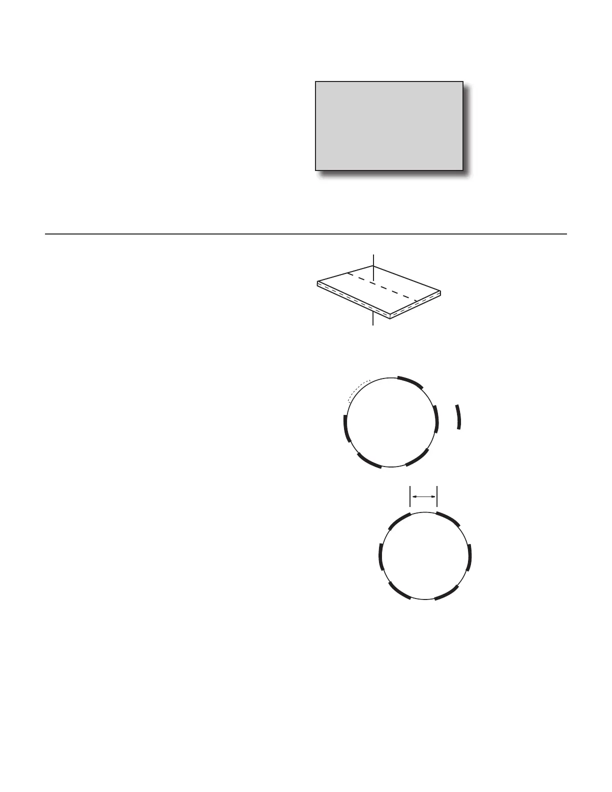
The magnets provided by Micro-Trak are marked with
a dashed line on the SOUTH pole side of the magnet.
See Illustration 3A.
Always use an even number of magnets, and always alternate
the polarities of the magnets as you go around the wheel
hub or drive shaft.
To install, mount the first magnet with the SOUTH pole side
(dashed line) facing toward the hub or shaft. Mount the
second magnet with the NORTH pole side facing toward the
hub or shaft. See Illustration 3B.
For proper operation, the magnets must be evenly spaced
around the wheel or drive shaft. The magnets must be at
least 1” apart. See Illustration 3C.
Illustration 3A
Illustration 3C
Illustration 3B
N
North
North
North
South
South
South
1
2
4
3
5
6
should alternately
attract and repel.
1” Minimum