19
CIRC: This position is used to calibrate the speed sensor
for ac cu rate speed and dis tance measurement. When this
position is selected, the display will alternately show, every
three seconds, the wheel
circumference value and
the distance value. The
wheel circumference value
is the number shown along with “CAL” on the
display. See Illustration 17B. The distance
value is the number shown when “CAL” is not shown on the
display. Either one may be selected to calibrate for speed
and distance measurement. Select by pressing the “+” or “-”
button when the desired value is being displayed.
Working Width
Banding Application Calibration
In banding applications, you will still need to enter the total
width of each boom section so that area counts correctly, but
you must also calculate the percentage of your total width
the band is covering and reduce your target rate to match.
For example, if you are planting with an eight-row planter
with 30-inch spacing, your total working width, regardless
of the width of bands, is 240 inches (8 x 30 inches). Now, for
purposes of this example, you have eight 12” bands. Your
total band coverage is 96 inches (8 x 12 inches). Based on
that, your band is covering 40 percent of your total width
(96 divided by 240). If you want to apply 20 GPA in the
band, enter 8 GPA as your target rate (40 percent of 20 GPA).
See Illustration 17A.
To determine circumference, measure the
distance of one complete wheel revolution
and divide by the number of magnets installed .
Determining Wheel Circumference
For the console to calculate the correct number of acres
(hectares), both the circumference of the sen sor-equipped
wheel and the implement width must be entered. Determine
the circumference of the sensor-mounted wheel to the
nearest tenth of an inch (thousandth of a meter) with the
fol low ing method:
METHOD
Mark tire with a piece of chalk and mea sure distance traveled
on the ground for one com plete rev o lution. See Illustration 19.
For accuracy, measure the wheel rev o lu tion sever al times and
take the average. Divide that val ue by the num ber of magnets
installed on the wheel hub to get your starting wheel cir cum-
fer ence (CIRC) calibra tion val ue.
Illustration 17A
Illustration 17B
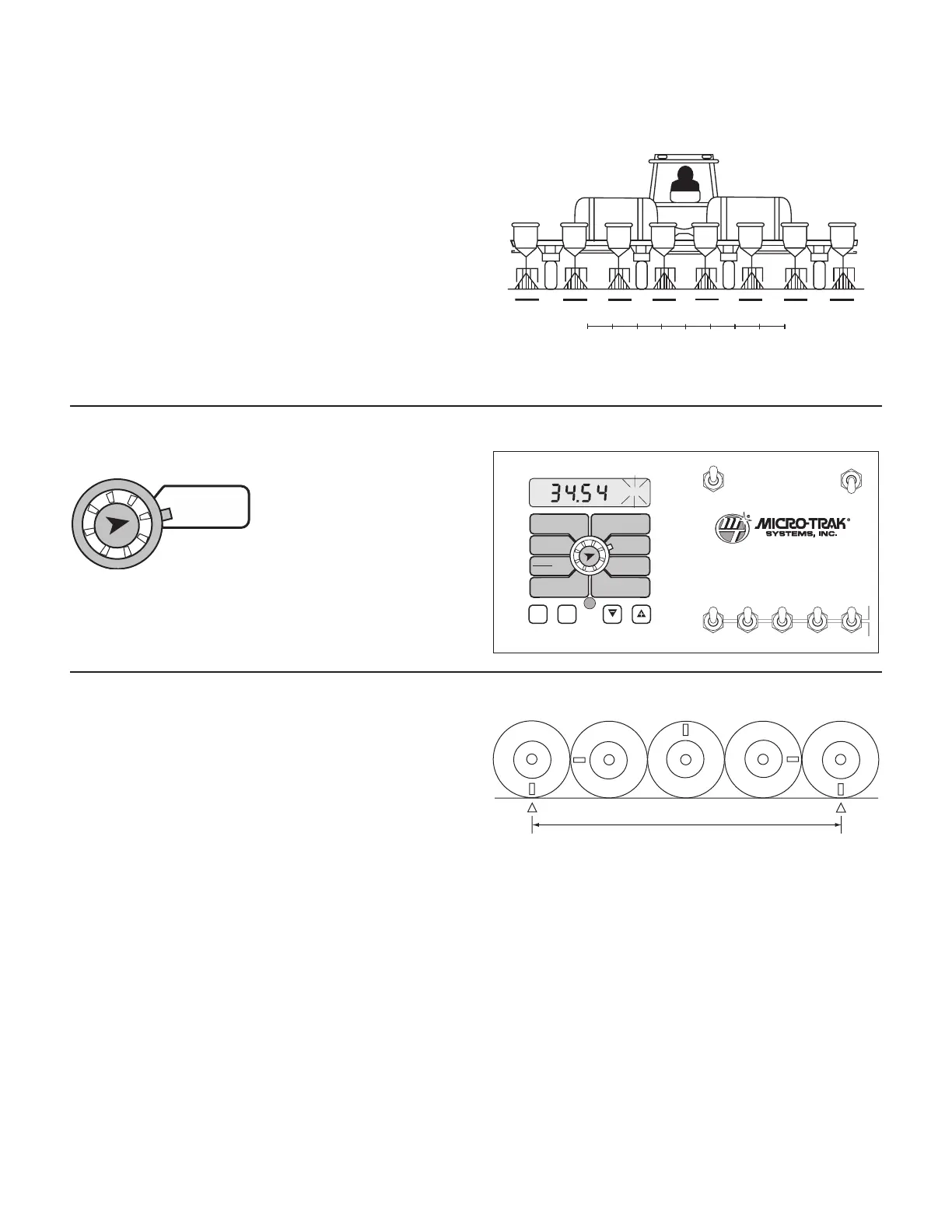
Illustration 18
Calibration (cont)
Entering Calibration Values (cont)
+
+
+
+
+
+
+
WIDTHBOOM
SELECT
TEST
SPEED
ADJUST
RATE
TARGET
RATE
CIRC
MIN
FLOW
FLOW
CAL
SPEED
DISTANCE
FLOW
RATE
TOTAL AREA
APP. RATE TOTAL FLOW
SUB AREA
ON
OFF
ON
OFF
12345
B O O M S
RUN
HOLD
AREA
HOUR
CAL
AUTO
MAN
RESET
MT-3405
™
F
AUTOMATIC RATE CONTROLLER
MANAUTO
CALHOLD
V 1 2 3 4 5
CIRC
DISTANCE