11
Attaching Magnets
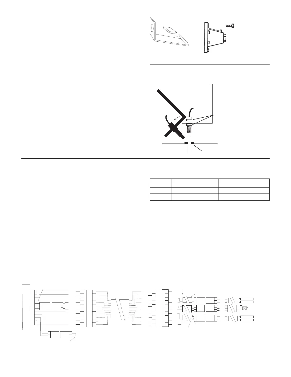
Refer to the following diagram for general mounting
instructions. For specific mounting instructions, refer to
Appendix A in the back of this manual.
NOTE: Magnets may be attached mechanically as shown or
adhered with epoxy or other high quality adhesive. When
using adhesive, thoroughly clean the area of dirt and oil.
The magnets are attached to a wheel hub or drive shaft and
the speed sensor is mounted directly over the magnet. When
the wheel or drive shaft begins turning, a speed impulse
is sent to the MT-3405 FTW console every time a magnet
passes by the tip of the speed sensor. For the speed sensor
to operate properly, the spacing between the magnets and
the tip of the sensor must always remain constant. Before
permanently mounting any parts, be sure that the location
you have selected will meet the following requirements.
See Illustration 4.
Installation (cont)
Speed Sensor Installation (cont)
Illustration 4
45° max
Sensor
(Green body)
3/8” nuts
Bracket must
be rigidly
mounted
be mounted more than
45° from perpendicular
¼” to ½” air gap
Drill lug bolt hole
and bend to fit hub.
Magnet
Connecting the Speed Sensor Cable
The speed sensor cable has a GREEN sensor body and mates
with the main harness cable having a YELLOW cable tie near
the 3-pin M/P connector. Make certain that you install the
correct sensor cable and connect it to the correct connector
on the main harness. The speed sensor and the flow sensor
are identical, but must be connected to the proper harness
connector. The speed sensor always connects to the main
harness lead with the YELLOW tie and flow sensor always
connects to the main harness lead with the GREEN tie.
See Illustration 5.
INSTALLATION NOTE: The main harness provides two
connection points for the speed sensor. For speed sensor
installations in the cab or near the control console, it
may be more practical to use the local access connector
(YELLOW tie) on the control console pigtail exiting the rear
of the console. Using this connection point will disable
the connection point on the end of the main harness. For
speed sensor installations on implements, it may be more
practical to use the speed connector on the end of the
main harness. When using this connection point, make
certain that the local access connector for speed/distance
is mated together.
The Run/hold sensor, which plugs into the other main
harness cable, also uses the same type of connector as the
speed and flow sensors. However, the Run/hold sensor has a
GRAY tie near the 3-pin connector, the sensor body is BLACK,
and it always connects to the main harness lead with the
GRAY tie.
Illustration 5
SENSOR IDENTIFICATION CHART
SENSOR SENSOR BODY COLOR MAIN HARNESS TIE COLOR
Speed Green Yellow
Flow Green Green
BOOM FIVE
DISTANCE
RED
ORG
YEL
GRN
BLU
VIO
N/C
N/C
BLK
BRN
A
B
C
D
E
F
G
H
J
K
10-PIN METRI-PACK TOWER
A
B
C
D
E
F
G
H
J
K
10-PIN METRI-PACK SHROUD
A
B
C
3-PIN
M/P 150
TOWER
LOCAL ACCESS SPEED CONNECTOR
BOOM FOUR
MT 3405 FTW CONSOLE
REMOVE JUMPER WIRE
TO CONFIGURE FOR BALL VALVES.
YELLOW TIE
A
B
C
3-PIN
M/P 150
SHROUD
A
B
2-PIN
M/P 150
SHROUD
A
B
2-PIN
M/P 150
TOWER
BRN
RED
ORG
YEL
GRN
BLU
VIO
GRY
WHT
BLK
A
B
C
D
E
F
G
H
J
K
A
B
C
D
E
F
G
H
J
K
10-PIN METRI-PACK TOWER
10-PIN METRI-PACK SHROUD
N/C
RED
BLK
RED
WHT
BLK
BLK
N/C
N/C
RED
3-PIN
M/P 150
SHROUD
A
B
C
YELLOW TIE
2-PIN
M/P 150
SHROUD
A
B
BLACK TIE
YELLOW TIE
GREEN TIE
A
B
A
B
A
B
2-PIN
M/P 150
TOWER
2-PIN
M/P 150
TOWER
2-PIN
M/P 150
SHROUD
3-PIN
M/P 150
TOWER
A
B
C
RED
BLK
RED
BLK
RED
WHT
BLK
FEMALE .250 QD
FEMALE .250 QD
FEMALE .250 QD
FEMALE .250 QD