9
Introduction
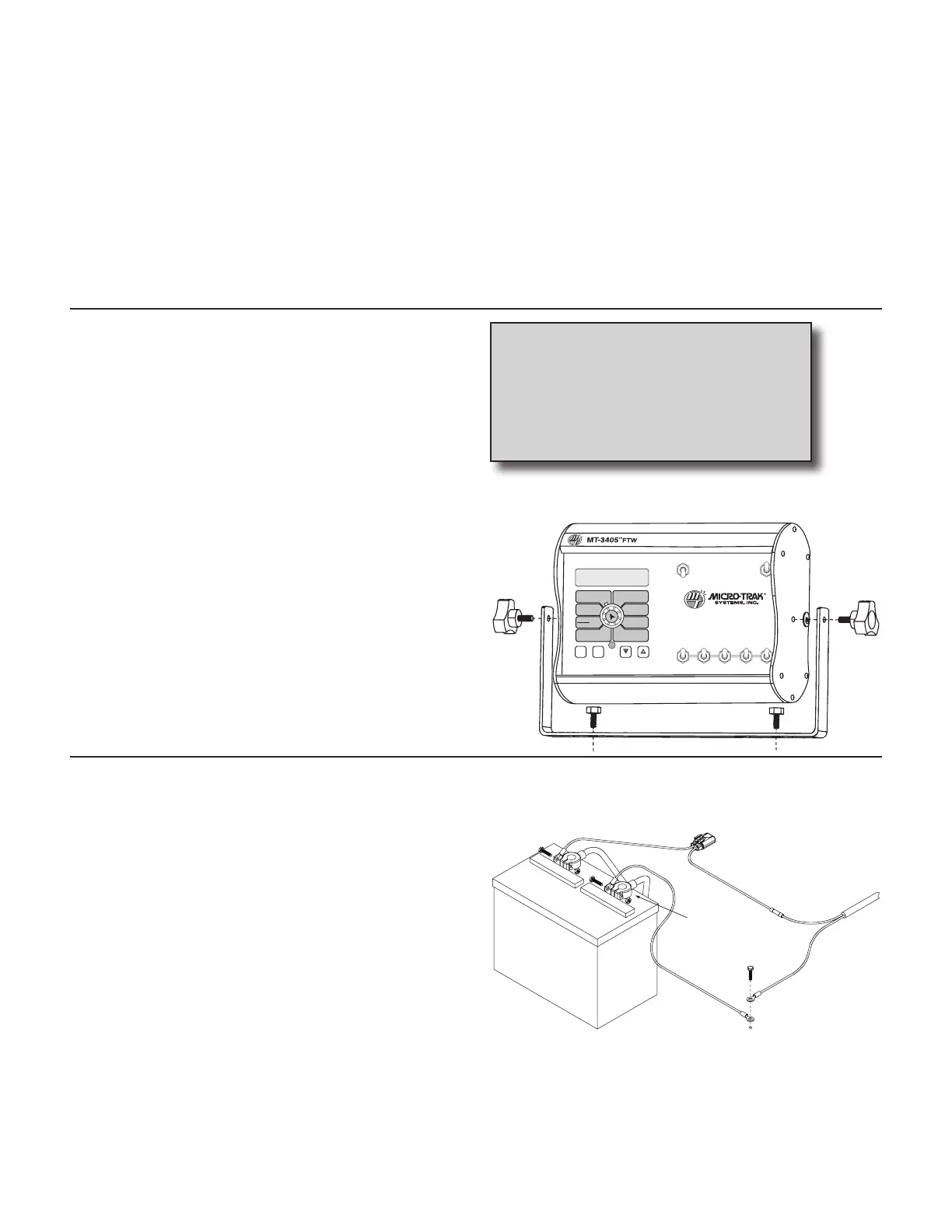
MT-3405 FTW
Select a mounting location which seems most workable,
and that best fits your needs. It should be con ve nient to
reach and high ly vis i ble to the op er a tor. DO NOT IN STALL
IN A PO SI TION THAT OB STRUCTS THE VIEW OF THE ROAD
OR WORK AREA. Whenever pos si ble, avoid lo ca tions that
expose the con sole to direct sun light, high tem per a ture,
strong chemicals or rain.
Place the mounting bracket in the selected lo ca tion, mark
holes, drill 1/4” (7mm) holes and mount bracket with bolts,
lock wash ers and nuts pro vid ed. (If bolts are not practical, use
self-tapping screws.) See Illustration 1.
Insert the console in the “U” bracket and install the console
knobs through the bracket, placing a rubber washer over the
threaded stud. Position console to proper viewing angle and
tighten the knobs securely.
Illustration 1
Tools Needed to Install MT-3405 FTW
• Screwdrivers • Pliers
• Set of Wrenches • Wire Cutter
• Electric Drill and Bits • Hammer
• 12-Volt Test Light • Hacksaw
• Center Punch • Bench Vise
The MT-3405 FTW is a flow-based control system which is
designed to be used on sprayers with diverting (three-way)
boom valves.
Using typical boom valves and a Micro-Trak flow-based rate
control system, when one of more of the boom sections are
turned off, the flow of liquid is discontinued to that boom
section, and flow is adjusted through the remaining boom
sections so that application rate (when in automatic) is not
affected.
Using the diverting (three-way) valve and the MT-3405 FTW
flow-based control system, liquid is actually diverted or
by-passed back to the tank. With the special “FTW” software,
the MT-3405 FTW counts only the liquid that has been
sprayed.
The MT-3405 FTW system uses individually entered boom
widths to determine which portion of the total liquid is being
by-passed rather than sprayed from the boom section. For
this reason, it is extremely important to adjust and verify
the amount of liquid that is diverted by the three-way valve
when a boom is shut off. Please read your sprayer’s operating
manual for details, or see Appendix C for basic instructions.
Installation
Mounting the Display Console
WIDTHBOOM
SELECT
TEST
SPEED
ADJUST
RATE
TARGET
RATE
CIRC
MIN
FLOW
FLOW
CAL
SPEED
DISTANCE
FLOW
RATE
TOTAL AREA
APP. RATE TOTAL FLOW
SUB AREA
ON
OFF
12345
B O O M S
RUN
HOL
AREA
HOUR
CAL
AUTO
MAN
RESET
MT-3405
™
F
AUTOMATIC RATE CONTROLLER
MANAUTO
CALHOLD
V 1 2 3 4 5
AUTOMATIC SPRAY RATE CONTROLLER
Electrical Installation
The MT-3405 FTW must be connected to a 12-volt DC elec-
tri cal system. Power is connected directly to the battery. The
MT-3405 FTW has an ON/OFF switch on the console to turn
the power off when the system is not being used.
Locate the power cable harness and connect to the mating
connector on the console. Connect the blue chassis ground
wire to a good frame ground. See Illustration 2. Make sure
there is good metal-to-metal contact. Route the power cable
from the console to the battery. Cut off excess length. In
routing cable to battery, avoid ar eas where the ca ble may
be subjected to abra sion or ex ces sive heat. Install the in-line
fuse provided with the kit on the white wire, as illustrated,
to protect the circuit. Connect the WHITE wire (hot) to the
positive battery terminal. At tach the BLACK wire (ground) to
a screw or bolt on the equipment frame. See Il lus tra tion 2. Be
sure there is good metal-to-metal con tact.
Your MT-3405 FTW is equipped with an ad vanced electronic
mem o ry which does not re quire a con stant supply of pow-
er to re tain daily totals or calibration values. The advantage
Hot
(WHITE)
Fuse Required
Chassis Ground
(BLACK)
Ground
Illustration 2
NOTE: For negative ground systems ONLY.
with this type of memory is that it conserves battery power
and will not dis charge the vehicle’s battery when equipment
is not in use.