39
NOTE: This is an optional method generally used on
pickups or custom vehicles. It may also be nec es sary on
any other vehicles where ac cess to the wheels is lim it ed.
This in stal la tion requires a spe cial calibration procedure,
see page 24.
Determine the best location for the magnets on drive shaft
according to which is the most practical spot to attach sensor
mounting bracket. This position should be no more than 12”
(.30 meters) behind the front U-joint. For best results, mount
“L” bracket to transmission and mount magnets on drive
shaft as close to transmission as pos si ble. This will en sure
prop er alignment if drive train shifts under heavy loading.
Two magnets are required for proper Hall-effect speed
sensor operation. Position them exactly opposite each other
(180 de grees apart). The polarity (north and south poles)
detect ed by the Hall-effect speed sen sor must alternate as
the shaft is turned. The magnets provided by Micro-Trak are
marked with a punched dashed line on the SOUTH pole side
of the magnet.
• Attach magnets onto drive shaft, one NORTH pole side
out and the other SOUTH (dashed) pole side out, by
wrapping ca ble tie around shaft and magnets. Position
each mag net so that its longest dimension moves in
the di rec tion of rotation. Pull cable tie tight and trim
off excess. An adjust able, non-magnetic (stain less steel)
band clamp may also be substituted.
Appendix A (cont)
Mounting on Drive Shaft
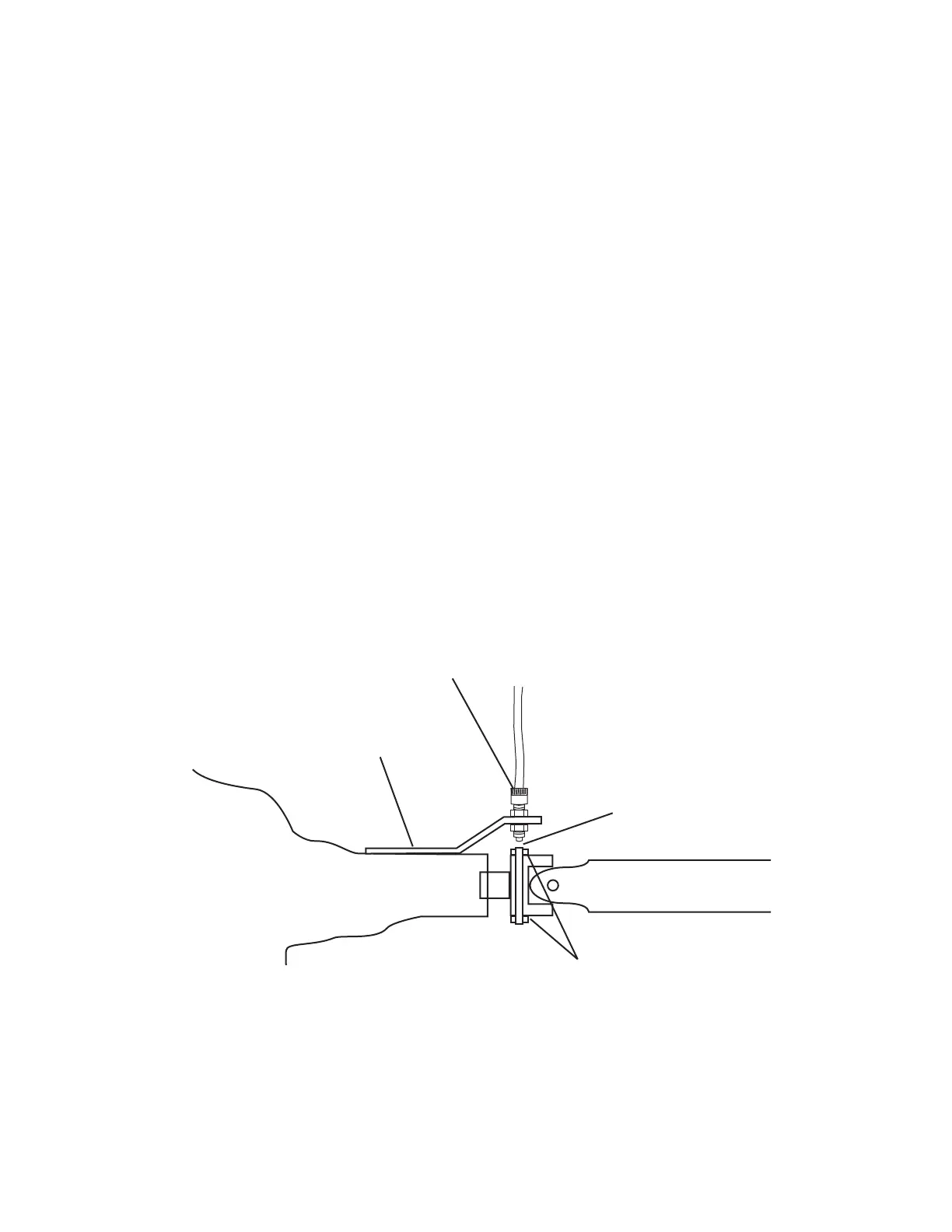
• Attach sensor bracket to vehicle transmission
with bolts, lockwashers and nuts provided. See Illustration
below. (Use self-tapping screws if bolts are not prac ti-
cal.) Use either the short or long end of the brack et as
a base. (Allow enough room be tween the bracket and
the magnets so that when prop erly spaced, the tip of
the sensor will extend 1/4” [7mm] or more be yond the
lock ing nut.)
• Turn one locking nut onto threaded sensor and in sert
sensor into large hole selected on mount ing brack et.
Turn on remaining locking nut. Set sensor to proper
distance from magnets (1/4” to 1/2”, or 6mm to 13mm).
When distance is set, tight en nuts to lock sensor in
place.
• Secure sensor cable to frame with cable ties. Place first
tie as close to sensor assembly as possible.
NOTE: If you are using more than two magnets, please
follow the directions on page 11.
ransmission/ Transfer Case Drive Shaft
Magnets Positioned
¼” to ½”
(6mm to 13mm)
Spacing
(Green)
Fasten Sensor Bracket with
Existing Transmission Bolts
or Rigidly Attach with Clamps.