13
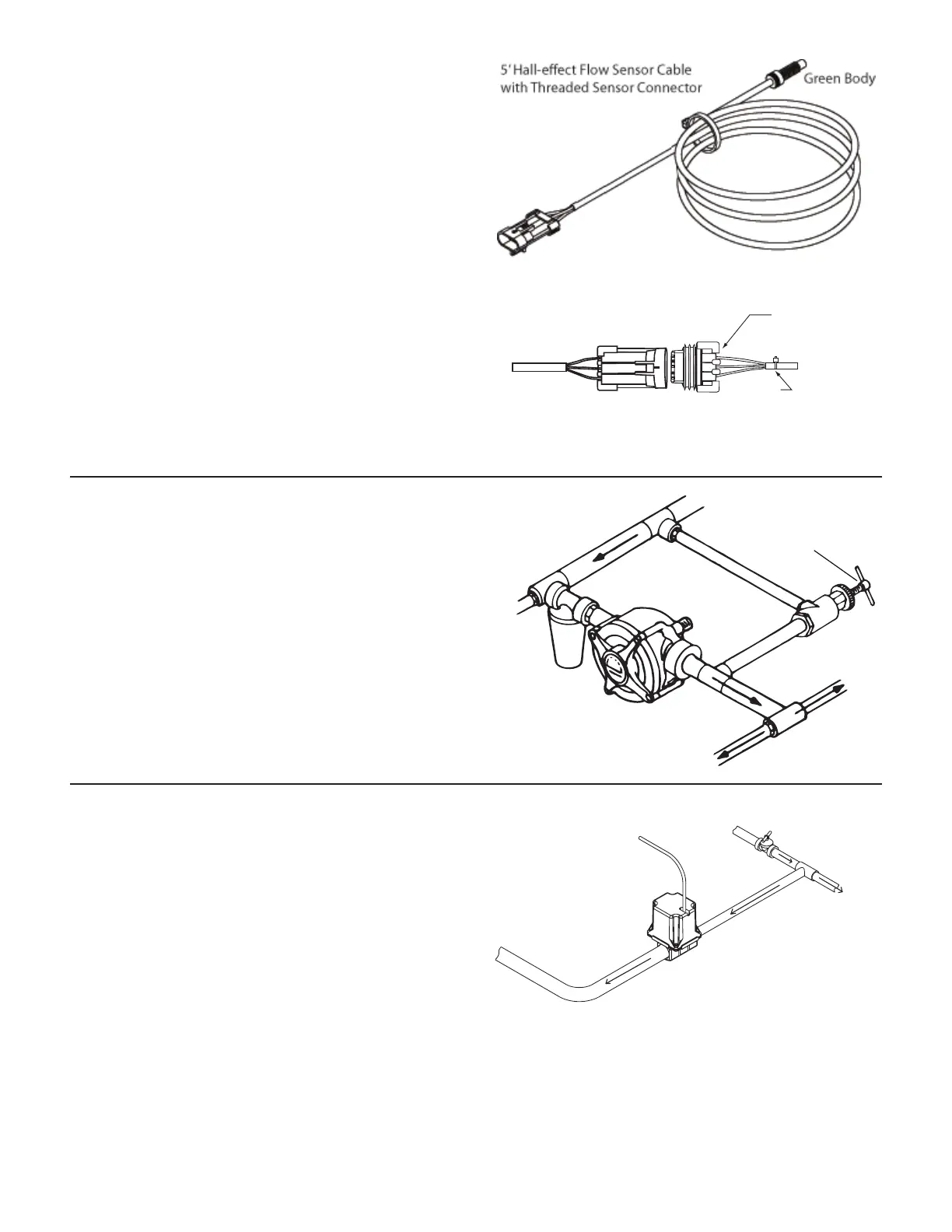
With the flowmeter in place, install the flow sensor cable
(GREEN body).
Screw sensor all the way into hole of flow me ter. Tight en 3/8”
jam nut to lock sen sor in place.
Uncoil flow sensor cable and carefully route it to meet the
main harness flow connector marked with GREEN tie. Align
connectors and press firmly together until locking tab clicks
into place. Secure cable with ties provided. See Illustration 7.
Connect flow sensor cable to green-tie console cable.
Installation (cont)
Installing Flow Sensor Cable
Illustration 7
A B C
C B A
Flow Sensor
Cable Connector
Main Harness
Flow Connector
Green Tie
Pressure Relief Valve
If you have a positive displacement pump or a cen trif u gal
pump capable of generating excessive pressure, you must
in stall a pressure relief valve and adjust it to a safe max i-
mum pressure. If a positive dis place ment pump is operated
without a pressure relief valve, damage may re sult to pump
or other plumbing component. See Illustration 8.
For Positive Displacement Pump
Illustration 8
Tee “C”
Tee “A”
Pressure
Relief Valve
Servo, Throttling Valves
The servo valve installs in an unrestricted return line to the
inlet of the pump or directly into the tank. DO NOT install the
servo valve closer than 12” to the flowmeter. The servo valve
has a flow direction decal on it. Make certain that the actual
flow direction matches the decal on the servo valve. DO NOT
install the servo valve in the agitation line. Slow response
time and marginal operation may result. The return line
should tee from the main line just after the throttling valve.
See Illustration 9. The throttling valve is used to limit the
output (set maximum output) of the pump to the flowmeter
and servo valve. The throttling valve is adjusted to put
the servo valve in its optimal operating range. Please refer
to Pre-Field System Checkout for proper valve adjustment
procedure.
The servo valve connects directly to the main harness 3-pin
W/P cable lead. If more length is required, use a 3-pin W/P
extension cable of the appropriate length. If using a Braglia
Illustration 9
Return to pump
inlet or unrestricted
return to tank
Servo Valve Cable
From Pump
Throttling Valve
To Flowmeter
Servo Valve
or other 12-volt control valve, please refer to 12-Volt Control
Valve Calibration on page 39.
NOTE: The servo valve may be installed in the main spray
line. For in-line installations, you will need to cut the servo
cable and reverse the wires. Connect the RED wire to the
BLACK wire and vice versa. Failure to reverse the wires will
result in the servo valve operating backwards.