15
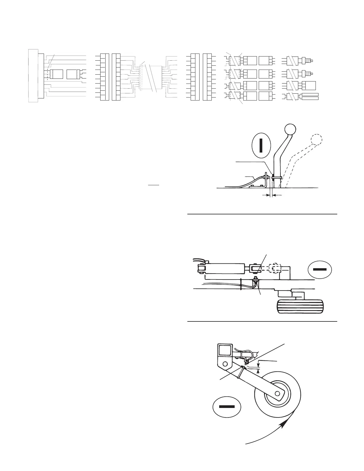
Lift Wheel Mounting
Hydraulic Cylinder Mounting
Remote Run sensor on hydraulic cylinder. Magnet and sensor
are in line when equipment is lowered and operating.
The run/hold sensor cable has a black body and a GRAY tie
near the 3-pin M/P connector and mates with the main har-
ness cable having a GRAY cable tie near the 3-pin M/P con-
nec tor. Make certain that you install the correct sen sor cable
and connect it to the correct connector on the main harness.
The run/hold sensor has a BLACK body. DO NOT use a speed/
flow sensor (GREEN body). See Illustration 13.
• Attach a magnet to a lever or some part of the equipment
that moves when the im ple ment is raised and lowered.
The Hall-effect run/hold sensor is sensitive only to the
south pole (side with dashed line) of the magnet. Check
the polarity of the magnet by bring ing it near the run/
hold sensor with the console turned on. Note and mark
the face of the magnet that is toward the sensor when
the console does not indicate “HOLD.” When the mag net
is away from the sen sor, the con sole will be in HOLD and
will shut off the boom valves and stop count ing acres.
NOTE: The run/hold kit includes a 5’ sensor cable
and 10’ extension. You may re quire additional
extension cables which are avail able in 5 ft. (1.5
m), 10 ft. (3 m), 15 ft. (4.5 m), 20 ft. (6 m) and 25 ft.
(7.6 m) lengths.
• You may also use a toggle or other type switch. Sim ply
cut the blue jumper wire in the dust cover and splice on
an appropriate length of wire to reach your switch.
When switch is closed, console is in RUN. When the switch is
open, the console is in HOLD.
INSTALLATION NOTE: The main harness provides two
connection points for the run/hold. For Run/Hold in stal la-
tions in the cab or near the control con sole, it may be more
prac ti cal to use the local access con nec tor on the control
console pigtail (GRAY tie) ex it ing the rear of the con sole.
Using this connection point will disable the con nec tion
point on the end of the main harness. For run/hold sensor
in stal la tions on im ple ments, it may be more practical
to use the run/hold connector on the end of the main
harness. When using this connection point, make certain
that the local access con nec tor is mated together.
Illustration 13
GREEN TIE
FLOW
SERVO
BOOM ONE
RUN/HOLD
BRN
RED
ORG
YEL
GRN
BLU
VIO
GRY
WHT
BLK
A
B
C
D
E
F
G
H
J
K
10-PIN METRI-PACK TOWER
A
B
C
D
E
F
G
H
J
K
10-PIN METRI-PACK SHROUD
A
B
C
A
B
C
3-PIN
M/P 150
TOWER
LOCAL ACCESS RUN/HOLD CONNECTOR
BROWN TIE
RED TIE
GRAY TIE
GRAY TIE
MT 3405 FTW CONSOLE
3-PIN
M/P 150
SHROUD
BRN
RED
ORG
YEL
GRN
BLU
VIO
GRY
WHT
BLK
A
B
C
D
E
F
G
H
J
K
A
B
C
D
E
F
G
H
J
K
A
B
C
D
E
F
G
H
J
K
10-PIN METRI-PACK TOWER
10-PIN METRI-PACK SHROUD
RED
WHT
BLK
RED
WHT
BLK
RED
BLK
RED
BLK
3-PIN
M/P 150
SHROUD
A
B
C
A
B
C
A
B
C
A
B
C
A
B
C
A
B
C
3-PIN
M/P 150
SHROUD
3-PIN
M/P 150
TOWER
3-PIN
M/P 150
TOWER
3-PIN
W/P 150
TOWER
3-PIN
W/P 150
SHROUD
2-PIN
M/P 150
SHROUD
2-PIN
M/P 150
TOWER
A
B
A
B
RED
WHT
BLK
RED
WHT
BLK
RED
WHT
BLK
RED
BLK
A
B
C
3-PIN
W/P 150
SHROUD
FEMALE .250 QD
FEMALE .250 QD
Installation (cont)
Remote Run/Hold
1/8” to 3/8 “ (6 mm to 13 mm)
space when equipment is
Sensor Cable
(black body)
Magnet
South
North
Run Position
Hold
Position
1/8” to 3/8”
(6 mm to 13 mm)
when wheels are up
Magnet
South
North
Run
Position
Hold
Position
Sensor
(Black body)
Magnet
North
South
Rockshaft Control Lever Mounting