14
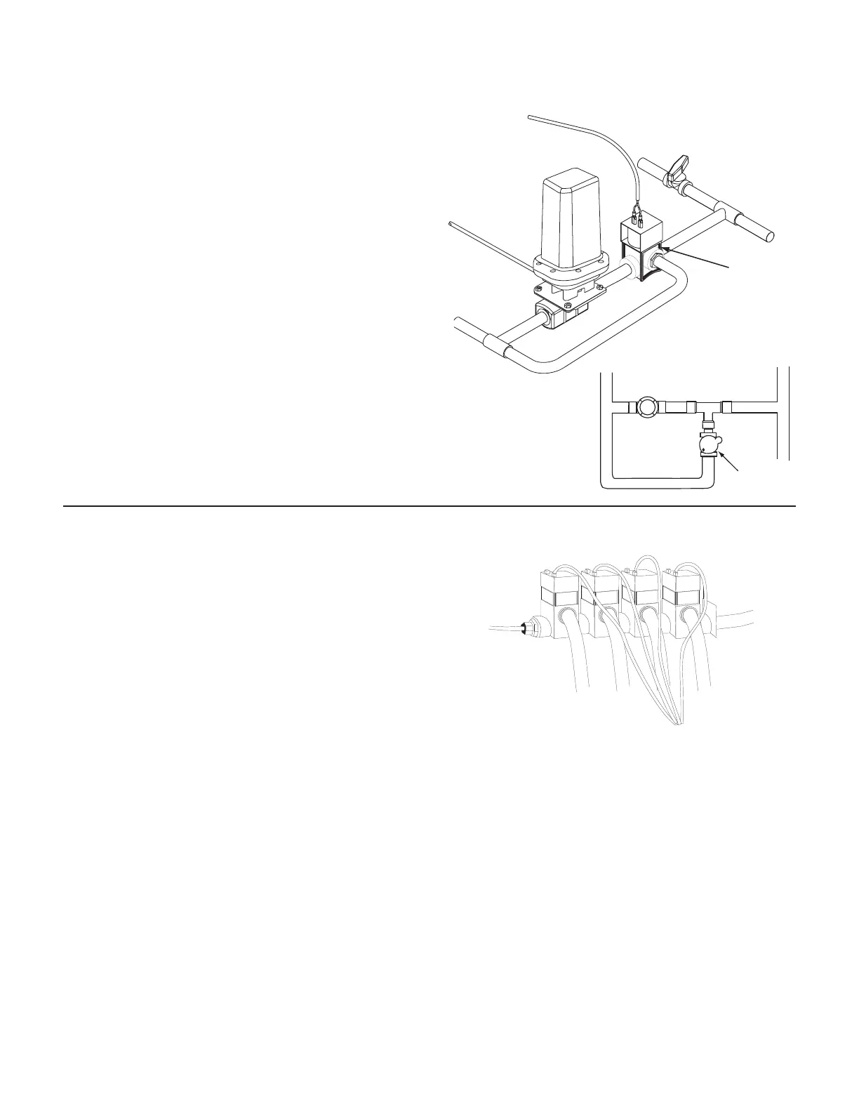
The relief valve is used to “dump” pressure when all boom
valves are turned off. Whenever all the boom control
switches are turned off, or when HOLD is selected with the
master switch, the relief valve should be open. Use this
plumbing illustration (See Illustration 10) as your pattern
for proper installation if your relief valve has a flow-through
port. DO NOT install the relief valve closer than 12” to the
flowmeter. Locate a 2-pin solenoid cable and connect it to
the relief valve using an appropriate method. Connect a
2-pin M/P connector to the module cable with no colored tie.
Be careful not to connect the relief valve cable to one of the
boom shut-off leads. All of the boom shut-off leads have a
colored tie near the 3-pin M/P connector. the relief solenoid
lead does not.
If all valves are NOT the same type (all solenoid or all ball
valves), refer to Appendix B for wiring instructions.
If your relief valve does not have flow-through port, you must
add a “T” fitting. See Illustration 11.
NOTE: To as sure a good con nec tion and avoid corrosion,
coat electrical connections with sil i cone grease.
Installation (cont)
Relief Valves
Illustration 11
Illustration 10
RELIEF SOLENOID
“T” Fitting
Servo
Valve
Relief
Solenoid
Boom Shut-off Valves
Locate the boom shut-off cables. Crimp the insulated female
spade terminals provided with the cables to both wires. (If
valves have wires, crimp terminals on those wires). Attach
the cables to the terminals on the boom valves. Normally,
wires connect red to red and black to black. If valves operate
backwards, reverse connections. Apply silicone grease to the
ter mi nal connections to help prevent corrosion and insure a
good electrical con nec tion.
Locate the colored cable ties included with the boom shut-off
cables. Attach a BROWN tie near the 2-pin M/P connector on
the boom one (1) cable. Attach a RED tie near the 2-pin M/P
connector on the boom two (2) cable. Attach an ORANGE tie
near the 2-pin M/P connector on the boom three (3) cable.
Attach a YELLOW tie near the 2-pin M/P connector on the
boom four (4) cable. Attach a GREEN tie near the 2-pin M/P
connector on the boom five (5) cable.
Connect the 2-pin M/P connectors to the mating con nec tors
on the main harness. Boom one (1) connects to the mating
connector with the BROWN cable tie near the con nec tor.
Boom two (2) connects to the mating connector with the
RED cable tie near the connector. Boom three (3) connects
to the mating connector with the ORANGE cable tie near the
connector. Boom four (4) connects to the mating connector
with the YELLOW cable tie near the connector. Boom five (5)
connects to the mating connector with the GREEN cable tie
near the connector. See Illustration 12.
Illustration 12
Boom 1
(Brn Tie)
Boom 2
(Red Tie)
Boom 2
(Org Tie)
Boom 2
(Yel Tie)