18
To enter or change any of the system’s calibration values,
you must enter calibration mode. To enter calibration mode,
STOP the vehicle, place the run/hold switch on the front
panel in HOLD and press and hold the CAL button until “CAL”
lights up (approximately three seconds). (NOTE: Calibration
may be entered while moving, but it is not rec om mend-
ed to attempt calibration while the vehicle is mov ing).
The console will remain in calibration mode, with the RED
warning light illuminated until you exit calibration or turn
power OFF.
Once in calibration mode, you may change any one, all or
none of the values, in any order.* To select a calibration
position, simply turn the rotary selector to the desired
position. Calibration positions are identified with white
lettering inside boxes that are outlined in GREEN, on each
side of the rotary selector. All values are entered and
adjusted using the “+” and “-” but tons on the front panel.
*Test speed must be last.
TARGET RATE: Enter the value for the
desired target application rate in gallons per
acre (liters per hectare). This is the ap pli ca-
tion rate that the control console will lock
onto when operating in
AUTO.
ADJUST RATE: Enter the value for the desired amount
of change in gallons per acre (liters per
hectare) to be used for making on-the-go
rate adjustments when
op er at ing in AUTO. For
example, if a value “1.0” is
entered, you will be able
to increase and decrease your application rate in one-gallon
(liter) increments during operation in AUTO. To disable this
feature, simply enter “.0” for a val ue.
TEST SPEED: Enter the value to be used for simulating
speed for perform ing Pre-Field System Checkout. The
console will use this
speed for simulating
spraying operations. The
test speed value is only
used while in calibration mode. Once CAL is
exited, the Test Speed value is reset to zero.
DO NOT ENTER A TEST SPEED UNTIL ALL OTHER VALUES
ARE PROPERLY ADJUSTED. Please refer to Pre-Field System
Checkout for details.
BOOM SEL: This position is used to select the boom
section to be calibrated. With the ro ta ry switch in this posi-
tion, the dis play will show
the ac tive boom section
num ber. Use the “+” and
“-” buttons to select the
boom section to be calibrated. Once the
desired boom section has been selected, turn
the rotary selector to width to enter the effec-
tive work ing width for that boom section.
Re peat this pro ce dure for each boom section.
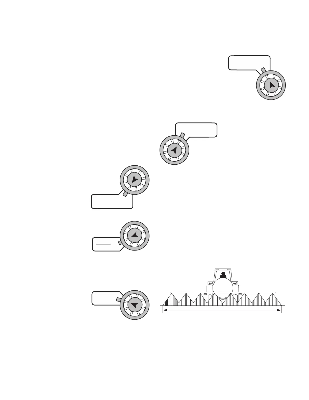
Setting Individual Boom Width
In order to accurately measure the number of gallons (liters)
applied per acre (hectare) it is important to determine the
correct “working” width. The “working” width is the width
of ground being affected by any operation. This should be
measured to the nearest inch (thousandth of a meter).
Your “working” width will vary depending on the type of
equipment you are using and the method of application.
For example, if you are broadcast applying chemicals your
“working” width will be the number of nozzles times the
nozzle spacing in inches (mm). For example, if you have 20
nozzles spaced at 20 inches, the working width is 400 inches.
See Illustration 16.
Working Width
WIDTH: Enter the effective working width, in inches (mil li-
me ters) for the boom sec-
tion currently shown on
the dis play. Re peat this
procedure for each boom
sec tion. Enter a value of “0” (.000) for any
unused boom sec tions.
Calibration (cont)
Entering Calibration Values
TARGET
RATE
APP. RATE
ADJUST
RATE
AREA
HOUR
TEST
SPEED
SPEED
BOOM
SELECT
TOTAL AREA
WIDTH
SUB AREA
Illustration 16