27
CONSOLE
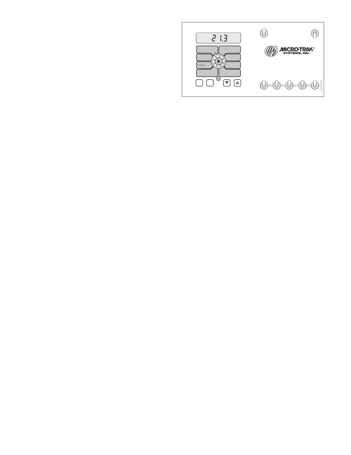
The MT-3405 FTW control panel features a large, easy-to-
read backlit liquid crystal display, exclusive BriteKnob
™
dial
and backlit panel for night operation.
POWER SWITCH
This switch controls 12-volt power to the entire system. In
the OFF position, there should be no drain on the vehicle’s
electrical system.
RUN/HOLD SWITCH
Selecting the RUN position will turn on all active boom valves
(provided Remote Run/Hold is NOT in HOLD) for AUTO or
MANUAL control operation. (Boom switches must be in the
ON position). Selecting the HOLD position will shut off all
active boom valves. (Boom switches may remain in the ON
position.)
NOTE: In AUTO, booms will not turn on without speed.
BOOM SWITCHES
The console accumulates area based on the calibrated
boom widths. When an individual boom is turned OFF,
the respective width is subtracted from the total width to
accumulate area based on the new active application width.
If a boom switch is ON, its respective boom shut-off valve
should be on. If a boom switch is OFF, its respective boom
shut-off valve should be off. No shut-off valves should be ON
if the Run/Hold switch is in HOLD, or in RUN and AUTO while
speed is zero.
AUTO/MAN BUTTON
This button will switch the control status of the system from
fully automatic to manual control. Each press of the button
will change the status. The display will show “AUTO” when
automatic control mode is active and “MAN” when manual
control mode is active.
CAL BUTTON
This button allows you to enter and exit calibration mode.
Pressing and holding the CAL button for approximately
three seconds will put the console in calibration mode. The
display will read “CAL” and the RED warning light will be
illuminated. Pressing and holding the CAL button again for
approximately three seconds will exit calibration mode and
return the console to normal operating mode. The display
will no longer read “CAL” and the RED warning light will turn
OFF.
Turn rotary dial to display desired readout.
Operation
Console and Switches
WIDTHBOOM
SELECT
TEST
SPEED
ADJUST
RATE
TARGET
RATE
CIRC
MIN
FLOW
FLOW
CAL
SPEED
DISTANCE
FLOW
RATE
TOTAL AREA
APP. RATE TOTAL FLOW
SUB AREA
ON
OFF
ON
OFF
12345
B O O M S
RUN
HOLD
AREA
HOUR
CAL
AUTO
MAN
RESET
MT-3405
™
F
AUTOMATIC RATE CONTROLLER
MANAUTO
V 1 2 3 4 5
“+” AND “” BUTTONS
These buttons are used to enter and adjust calibration values
when calibrating the system. During normal operation, when
automatic “AUTO” control mode is active and the rotary dial
is set to APP. RATE, each press of the “+” and/or “-” buttons
will increase and/or decrease the target application rate by
the amount of the calibrated adjust rate.
During normal operation, when manual “MAN” control mode
is active and the Run/Hold switch is in the RUN position,
pressing the “+” and/or “-” buttons will increase or decrease
the application rate by opening and closing the servo valve
(control valve).
During normal operation, when either automatic or manual
mode is active, the Run/Hold switch is in the HOLD position
and the rotary switch is turned to FLOW RATE, pressing the
“+” and/or “-” buttons will increase or decrease the pressure
for setting the proper agitation flow rate, without having the
boom valves turned on.
During normal operation, when either automatic or manual
mode is active, pressing and holding the RESET (“ - ”) button
will reset the TOTAL AREA, SUB AREA, DISTANCE or TOTAL
FLOW counter (the rotary switch must be turned to one of
those counters for the reset function to be active). Please
refer to Resetting System Counters for more details. The reset
function is not active when the Run/Hold switch is in the RUN
position or the console is in calibration mode.
WARNING DEVICE
The console is equipped with a RED warning light. The
light will automatically turn on and flash when the
actual application is plus or minus 10 percent from
the calibrated target rate. If this light stays on while
in AUTO, refer to the troubleshooting section of this
manual. The RED warning light will also be illuminated
when calibration mode is active on the console.