10. PCB MCU Connections
Important: In the PIC32MX/PIC32MM/PIC32MZ/PIC32MK family of devices, the function priority of any
pin is defined by the order of the signals left to right in the pin map tables. Any pin function utilized by the
user will override all listed functions to the right of it in the pin name.
10.1 Exposed Pad
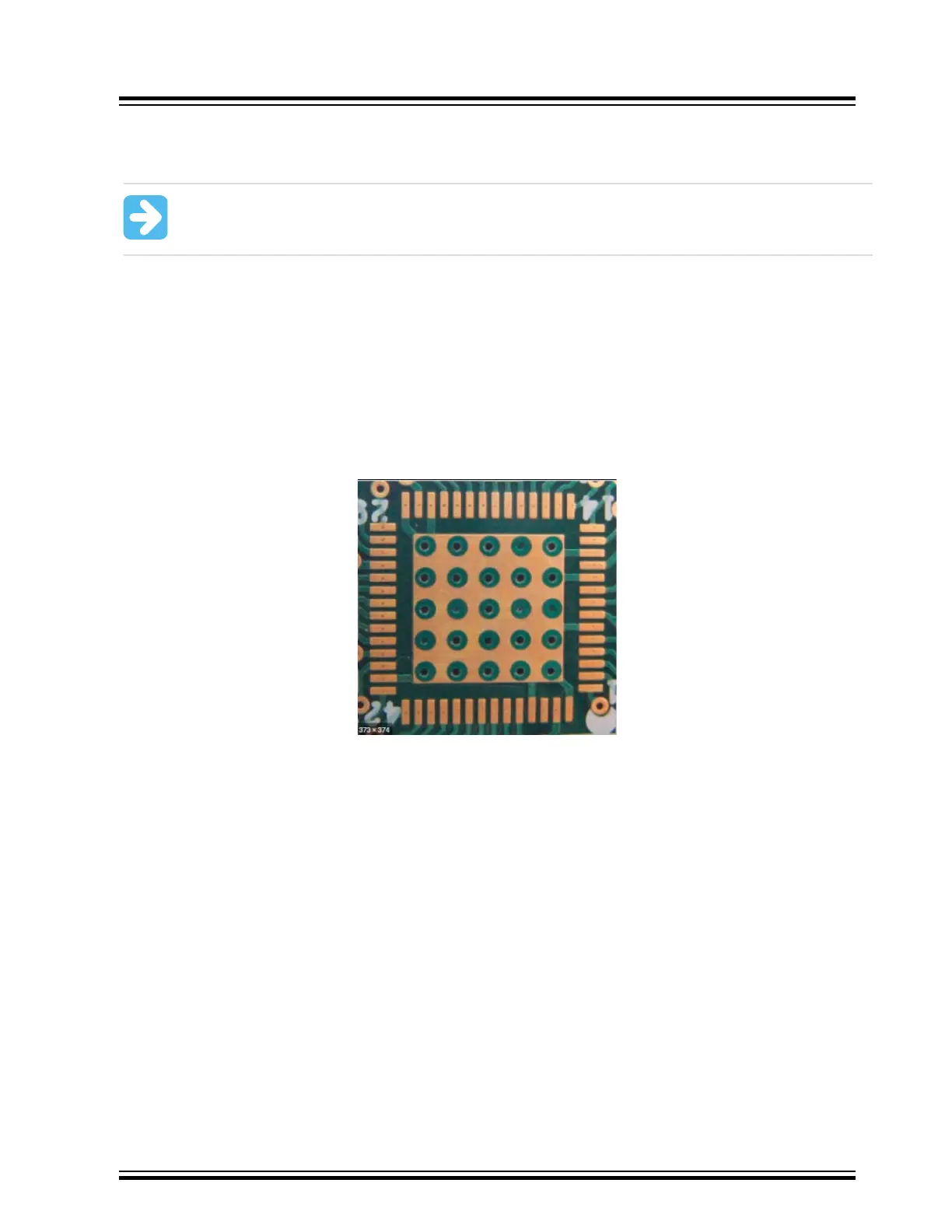
Problem 20: What needs to be done with the exposed pad on the MCU package for the PCB design?
The user must solder the exposed pad on packages that have them, to a matching perimeter ground landing beneath
the package punctuated with vias to the ground layer like indicated in the following figure. This is not a substitute
for the designated power ground pins on the device, they must still be connected to ground. This makes for easy
connections of ground pins to the ground plane.
Figure 10-1. Exposed Pad Landing Pattern Example
10.2 PIC32MX/PIC32MM/PIC32MZ/PIC32MK VUSB3V3 Pin
Problem 21: Some of the I/O pins and alternate function pins are not working at all even though they are configured
correctly
.
USB On-The-Go (OTG) consists of the following cable interface signals:
• D+ (Standard USB Data)
• D- (Standard USB Data)
• VBUS (Standard USB +5v)
• USBID (OTG Support, needs)
• VBUSON (OTG Support)
In the PIC32MZ/PIC32MK family of devices, the internal USB PHY transceiver, and therefore all of these interface I/O
pad signals are powered by the VUSB3V3, not the VDD. The standard USB signals in the list above are dedicated
pins and not multiplexed with any other alternate function or I/O. The USBID and VBUSON functions have alternate
functions and I/O mapping capabilities.
PCB MCU Connections
© 2022 Microchip T
echnology Inc.
and its subsidiaries
Manual
DS70005439B-page 30