Return to Checklist
11.3 SPI/SQI
Problem 27: Clock and data are present, but the target SPI device it is not responding.
•
The Serial Peripheral Interface (SPI) has four typical transmission modes for data. SCK polarity describes the
default idle state of the clock, and the SCK Phase/edge describes which edge of the SCK the data will be valid
on.
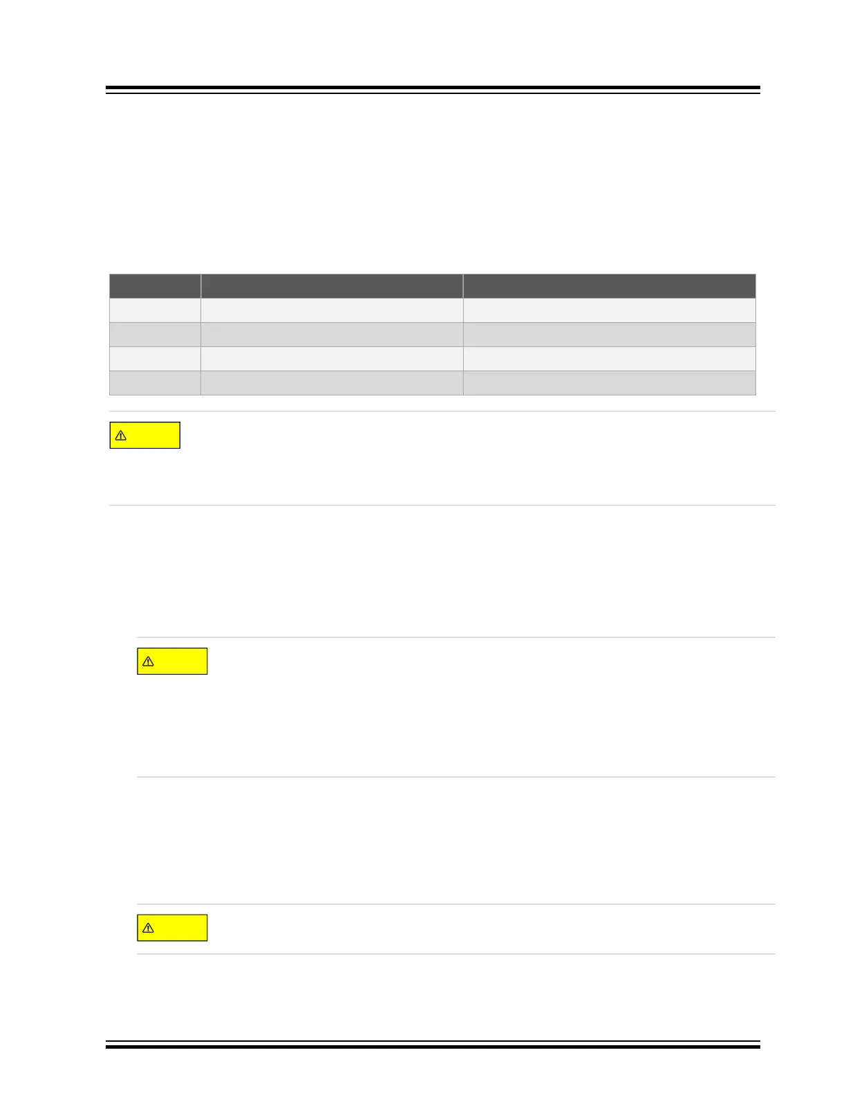
Table 11-2. SPI Modes of Operation
MODE 0 SCK Polarity – CPOL/CKP SCK Phase – CPHA/CKE
0 0 = SCK Idle Low 0 = Rising Edge Data Sampled
1 0 = SCK Idle Low 1 = Falling Edge Data Sampled
2 1 = SCK Idle High 0 = Falling Edge Data Sampled
3 1 = SCK Idle High 1 = Rising Edge Data Sampled
Most SPI peripherals on the SPI bus only operate or accept one or two modes of operation defined above
in the tables. All devices on the SPI bus must operate or be configured for the same mode. Ensure the
MCU SPI is configured in a SPI mode compatible with the remote SPI devices on the SPI bus. If either
of these requirements are not met the user will not have a successful SPI communication with the target.
Compare the MCU SPI settings with the SPI target peripheral data sheet modes.
Problem 28: Why is the SPI data always shifted by one bit?
•
In designs where there is only one SPI target in the system, designers often save pins simply by tying the target
SPI #CS to the ground in an effort to use only the minimum 3-wire SPI interface. In that case, the user must
ensure a proper pull-up if the SCLK polarity is idle high, or a pull-down if the Client SCLK polarity is idle low. The
SPI Host has a programmable SCLK polarity bit that the user sets to match the target default SCLK polarity. It
also has a programmable Clock Edge.
If a user selects the SPI clock edge to output data changes on transitions from the active clock state
to the Idle clock state and the clock polarity is idle high then, without a Host supplied chip select to
the target, when the MCU powers up the I/O pins used are T
ri-Sate and float low. When the SPI is
enabled and the I/O pin SCLK function is output, the pin will transition from the Tri-Stated floating
logic low to the SCLK idle logic high state. The target device will see this as a valid clock edge and
shift whatever is in the Client shift register Msb out, good, bad, or nothing. After this point on every
transfer will be off by one bit. It is highly recommend to use #CS even if there is only one target SPI in
the system to avoid this possibility.
Problem 29: Why is the SPI /SQI data corrupted?
•
In PIC32MX/PIC32MM/PIC32MZ/PIC32MK ensure to set the SPIxCON.SMP bit when in Host mode for the
fastest data dates. There is a significant speed difference available depending on the state of the SMP bit in
Host mode.
• There is also a difference in the maximum speed that the SPI can achieve depending on the following::
Use the dedicated SPI SCLK pin functions as opposed to the PPS remappable SCLK in PIC32MX/
PIC32MM/PIC32MZ/ PIC32MK families for higher speeds.
Serial Data Corruption Errors
© 2022 Microchip T
echnology Inc.
and its subsidiaries
Manual
DS70005439B-page 36