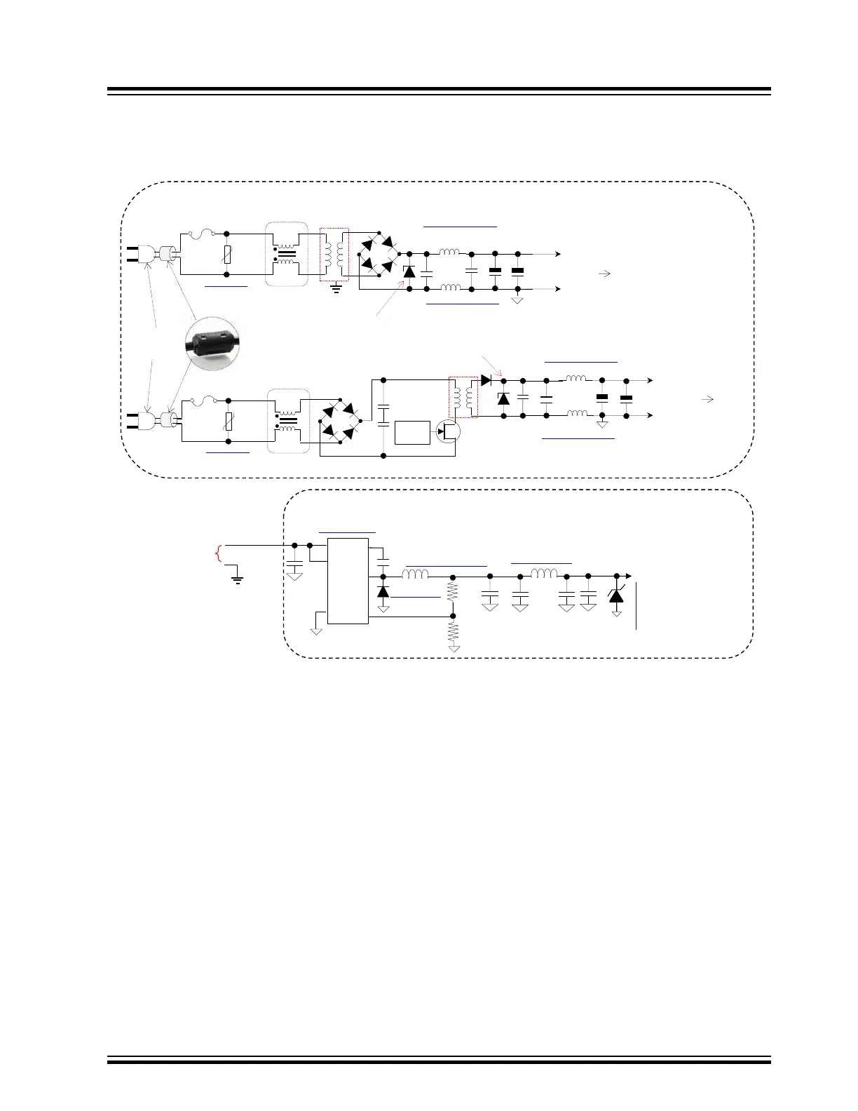
15. Inlet Power Protection Illustration
Figure 15-1. Power Source Input Protection Diagram
NOTE: Select unidirectional “Transient Voltage Suppressor”, TVS, such that the
“Reverse working voltage, VRWM” specification is ~(10%-20%)
more than maximum peak working voltage at the bridge
rectifier output.
22uf
3A@250v
MOV
(Metal
Oxide
Varistor)
SC‐03‐10G
MOV-10D201K
130VAC Line
Switch
Controller
Shielded
L
N
0.1uf
FBMH4532HM132-T
1.3k@100Mhz, DCR=0.06Ω, 3A
FBMH4532HM132-T
1.3k@100Mhz, DCR=0.06Ω, 3A
+
100uf
DC+
GND
To Regulator(s)
+
100uf
NOTE: The AC to DC Power circuits should be located on the AC Chassis Ground Plane if possible.
MOV
(Metal
Oxide
Varistor)
MOV-10D201K
130VAC Line
SC‐03‐10G
3A@250v
L
N
0.01uf
+
0.1uf
100uf
DC+
GND
To Regulator(s)
+
100uf
5
AP3211KTR-G1
VIN
EN
FB
49.9K
SW
4.7uhShielded
NRS5020T4R7MMGJ
4
3
6
2
1
GND
BS
10UF,25V
10%X7R
ESR < 1
4.5‐>12vdc
DB2L33500L1
10nf
16,3K
22uF
0.1uF
MI1206L501R-10
0.1uF
22uF
VDD=3.3v@1.5A
SMAJ5.0ATR
NOTE: The DC to DC power circuits should be located on the signal ground plane but as close
to the power ground, DC power inlet, from the AC to DC supplies as possible.
Power Cord
Ferrite
SMPS
Twisted Pair
Power Cable
FBMH4532HM132-T
1.3k@100Mhz, DCR=0.06Ω, 3A
FBMH4532HM132-T
1.3k@100Mhz, DCR=0.06Ω, 3A
echnology Inc.