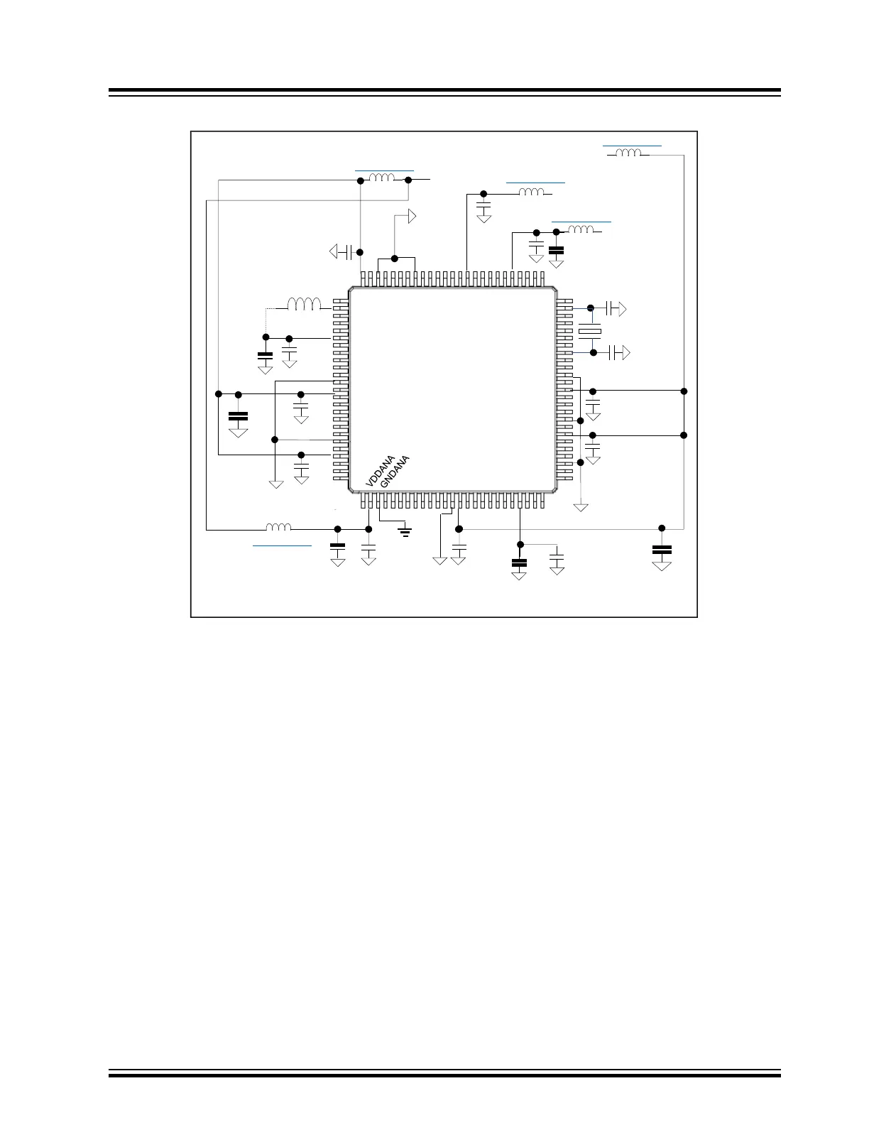
Figure 7-4. SAM/PIC32C Recommended Minimum CPU Power Bypassing
GND
VDDIOA
GND
GND
VDDIOB
GND
VDDIOB
VDDIOA
GND
GND
VDDIOA
GND
VDDIOA
GND
VDDIOB
0.1uf
0.1uf
PIC32C
SAMxx
XTAL
0.1uf
0.1uf
0.1uf
0.1uf
10µf
VDDIOB
1. VDDREG only present on some PIC32C variants.
2. If External VREF utilized.
VDDREG
VCORE
0.1uf
4.7µf
0.1uf
4.7µf
VBAT
0.1uf
10uf
10µf
VDDIOA
VDDANA
VCORE
VSW
MI0805J102R-10
MI0805J102R-10
LEXT:See
DataSheet
0.1uf
10µf
*(1) VDDREG
0.1uf
*(2) VREF
VREFx
MI0805J102R-10
MI0805J102R-10
MI1206L501R-10
Return to Checklist
7.3 Power Sequencing
Problem 3: The MCU is experiencing intermittent start-up and/or lock up issues on power-up.
•
There are strict limits on voltage variations between different supplies on an MCU during power-up. In the
PIC32MX/ PIC32MM/PIC32MZ/PIC32MK, the VDD and AVDD must be no more than 0.3V apart during power-
up. In the SAM/PIC32C it is VDDIO, VREG, and VDDANA. If using different regulators for different MCU
supplies, it is critical that the designer consider how to manage this. This becomes even more critical in designs
that use cascaded regulator designs (i.e., 5V > 3.3V > 1.8V regulators). This can create power sequencing
issues, as well as voltage ramp differential synchronization specification violations.
• In the case of the PIC32MX/PIC32MM, one result of the VDD and AVDD not tracking can be that the nominal
VCORE of 1.8V will saturate at the nominal VDD voltage level. For short periods of time this may not harm the
device, but will eventually induce reliability issues.
• To avoid unexpected current injection through the MCU, internal I/O high side protection diodes that can lead
to MCU POR and start-up issues, ensure that signals originating from separately powered circuits be powered
on after the MCU has been powered first. Failure to do so can cause an external logic high signal to power the
MCU. If that is not possible consider using signal logic isolators, such as opto, capacitive, or inductive coupling
components, see figures 7-1, 7-5B, and 7-6).
Note: Even the same regulator part number will ramp up at different rates depending on the load and bulk
capacitance of the power bus.
Return to Checklist
MCU Start-up Problems
© 2022 Microchip T
echnology Inc.
and its subsidiaries
Manual
DS70005439B-page 15