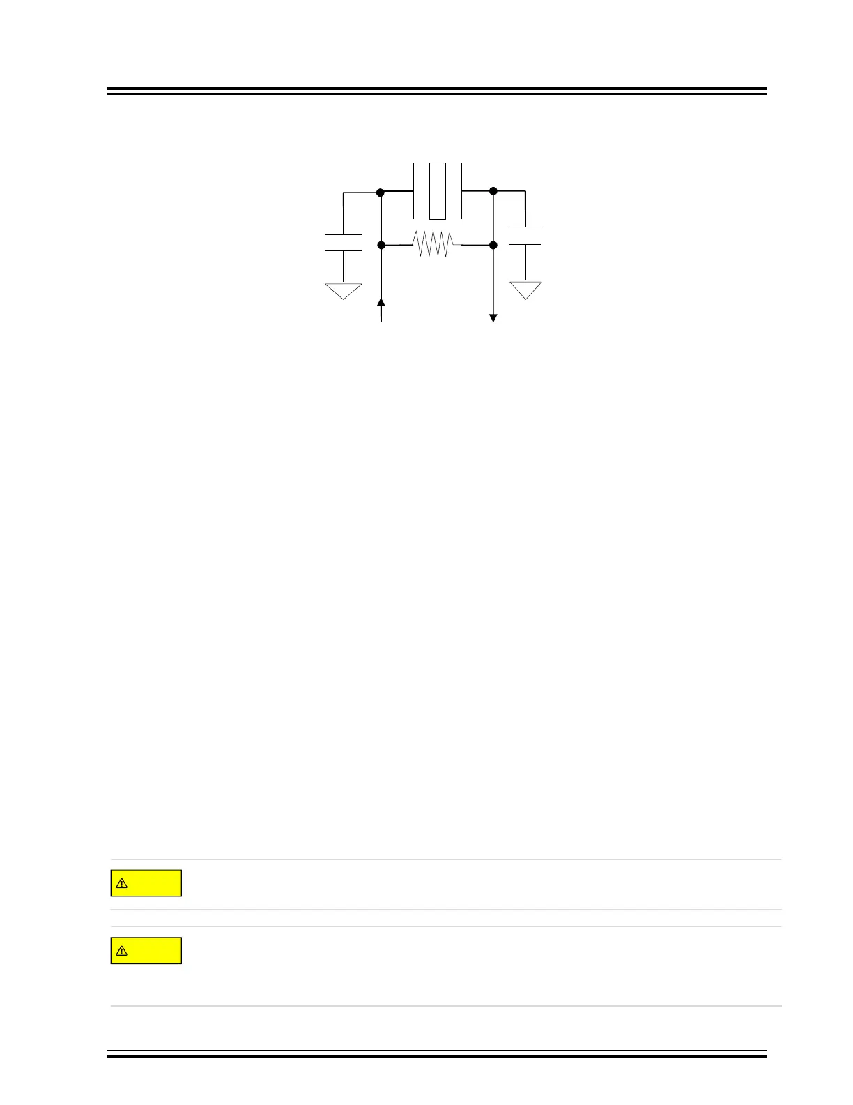
Figure 7-8. PIC32MX Typical Primary Oscillator Crystal Circuit
X
OUT
X
IN
C1
C2
RS
XTAL
OSC2
OSC1
RG= 1M
C1
C2
XTAL
Return to Checklist
7.6 Clock Switching
7.6.1 PIC32MX/PIC32MM/PIC32MZ/PIC32MK
Problem 10: The MCU operating frequency is not as expected or no MCU code is executing.
In these product families there exists the technical possibly to do either a silicon hardware clock switch or a
software clock switch which can sometimes lead to problems for an unwary user
. The configuration word control bits
associated with clock switching in these families are:
• IESO: Internal External Switchover bit
1 = Internal to External HDW Clock Switchover mode is enabled (Two-Speed Start-up is enabled)
0 = Internal to External HDW Clock Switchover mode is disabled (Two-Speed Start-up is disabled)
When IESO is set, the CPU hardware will start up executing code on the FRC and automatically switch to the
clock source defined by FNOSC when that oscillator source is ready and stable, regardless of whether or not
FCKSM clock switching is enabled.
• FCKSM: Clock Switching and Monitoring Selection Configuration bits
11 = Software run-time clock switching is enabled, and clock monitoring is enabled
10 = Software run-time clock switching is disabled, and clock monitoring is enabled
01 = Software run-time clock switching is enabled, and clock monitoring is disabled
00 = Software run-time clock switching is disabled, and clock monitoring is disabled
All configuration bits are set to “1” (i.e., Flash Erased Condition) by default unless the user explicitly defines each
and every configuration control bit. As result a user often wants to do a clock switch in software using the OSCCON
register at the beginning of their application code. Unfortunately, if the user forgot to clear IESO = 1 there exists the
possibility that:
While users code is attempting to do a software clock switch, the IESO hardware clock switch could
simultaneously be in progress resulting in neither clock switch being successful due to logic contention.
One of the two clock switches, HDW or SW, may be successful but which one is not always certain.
If the IESO HDW clock switch is successful, the final clock will be the one defined by FNOSC in the
configuration words. Otherwise, if the SW clock switch is successful then the clock source is defined by the
NOSC bits in the OSCCON register
.
MCU Start-up Problems
© 2022 Microchip T
echnology Inc.
and its subsidiaries
Manual
DS70005439B-page 21