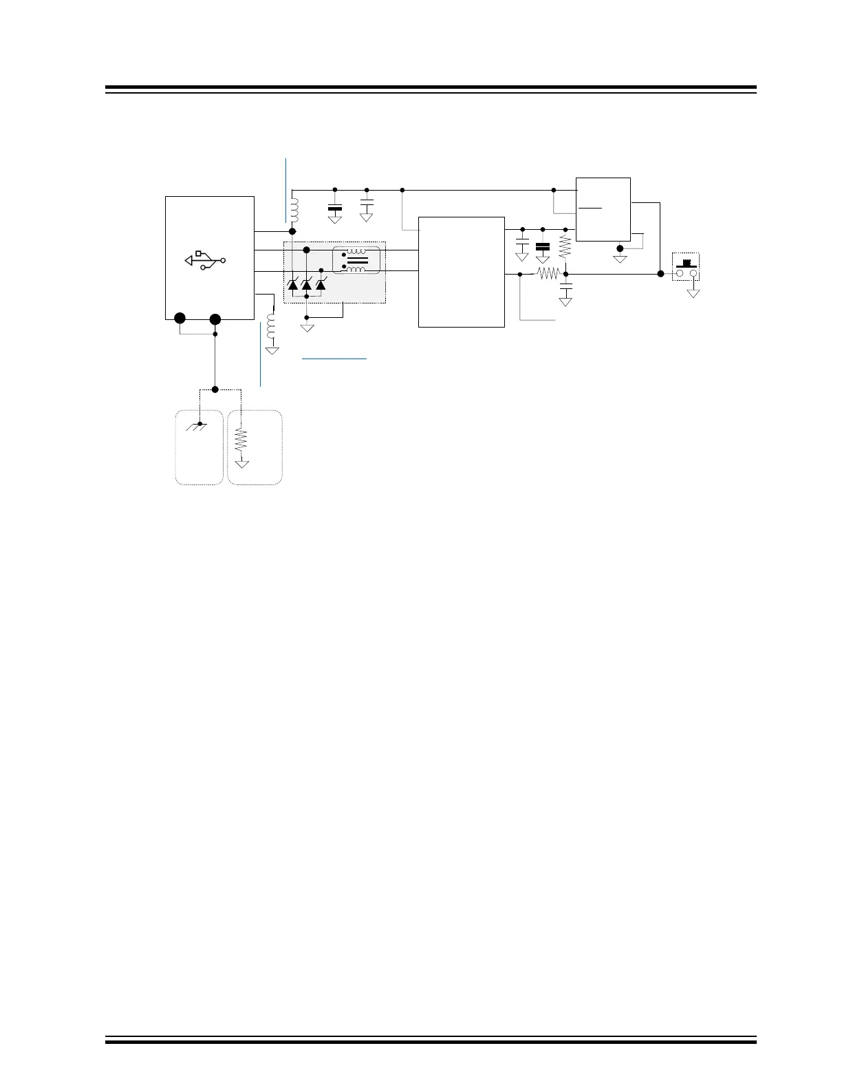
Figure 11-11. USB Device Design Example Diagram
USB 2.0 DEVICE PROTECTION EXAMPLE
6
VIN
VOUT
3,4,5
EMI2121
PAD
7
8
MCU
D-
D+
NOTE:
Ground connection on all TVS, Transient Voltage Suppressors, MUST be directly
connected to ground plane and not through a trace to ground to minimize inductance.
In addition, they should be located as close to the external USB Connector as possible.
1
2
NOTE:
USB D+ and D- differential controlled layout rules apply. PCB layout should maintain 90-
ohm controlled impedance. USB signals should not transition PCB layers, (i.e. no feed
through holes.), and no broken ground, (i.e. ground voids), beneath D+ and D-.
Opt(B)
Chassis
(AC) Gnd
if available
(Preferred)
If chassis (AC) Gnd
not available
Opt(A)
10K
VBUS
BLM31KN471SN1L
BLM31KN471SN1L
0.01uf
4.7uf
480 Ω @100Mhz,DC=0.02Ω, 4A
BLM31KN471SN1L
NOTE:
NOTE:
See appropriate MCU power
bypassing circuit configuration
illustrations in section 2.2
GND
2
1
4
3
5
RESET
USB 2.0
TYPE B
VBUS
D-
D+
GND
1
2
3
4
SHEILD
VDD
MCP1824T-3302E/DC
10k
0.1uf
1k
PWRGD
PAD
SHDN
ICSP (ICD4 / Real Ice #MCLR)
11.6.2 Key USB Device Design Points
• On the USB connector in the figure above, the shield is not directly tied to the digital signal ground which is a
typical design error
. Not connecting the shield to digital ground is to ensure that an ESD discharge event does
not infiltrate the digital ground system and disrupt normal application operation, generally resulting in an MCU
reset or component failure. Attach the shield to chassis ground. If chassis ground is not accessible, then connect
through either:
– 1 k Ohms @ 100 MHz Ferrite Bead 1A, DCR=0.15 Ohm for ESD protection only concerns, (i.e.
MI0805J102R-10).
– Recommended: A 10k fixed resistor which adds not only ESD protection, but ground loop current isolation
between the remote system shield / case and the local digital ground in the event that the remote system
did not follow good design practices. The 10k is a low enough impedance for the shield so that RF and EMI
interference is effectively attenuated to maintain the USB cable shield effectiveness.
• On the USB connector, the digital ground, pin 4, and the ferrite bead help to protect against a possible ESD
ground discharge event from the remote system. The normal series resistor is in line with the ferrite on many
other peripheral interfaces to limit potential ground loop currents, but is absent here due to the potentially large
USB downstream power requirements.
• The transient voltage suppressors and the 90 Ω common mode choke should be located as close to the USB
connector as possible. The common mode choke is only for conducted EMI isolation.
• The MCP1824T 3.3vLDO is shown to illustrate how it can also be used as a reset supervisor to the MCU.
Note: The required 1k isolation resistor is a requirement for the ICSP.
Note: There is comprehensive information available on ESD / EMI / EFT on our web site that can be found in the
document: AN2587 - EMI, EMC, EFT, and ESD Circuit Design Consideration for 32-bit Microcontrollers, or on any of
the 32bit product web pages under Documentation Tab > Application Notes.
Return to Checklist
11.7 CAN FD
Problem 37: Why is the CAN sending message errors?
Serial Data Corruption Errors
© 2022 Microchip T
echnology Inc.
and its subsidiaries
Manual
DS70005439B-page 47