7.5.4 Crystal Loading Capacitors
Crystal loading capacitors affect not only the crystals but the Automatic Gain Control circuits ability to oscillate. Many
users mistakenly assume that the load capacitors they must use in their circuit design are the crystal manufacturer
recommended load capacitors. The crystal manufacturers recommended C
LOAD
value in fact represents the
recommended EFFECTIVE
circuit capacitance, not the actual literal capacitance to use.
Notes: Crystal series limiting resistance is not required if the MCU Automatic Gain Control features are used or
if no XOSC signal clipping is seen. To calculate the equivalent effective capacitance for selecting the crystal load
capacitance:
Equation 1: Crystal MFG C
LOAD
= {( [C
IN
+ C1] * [C
OUT
+ C2] ) / [C
IN
+ C1 + C2 + C
OUT
] } + oscillator PCB stray
capacitance
Assuming C1 = C2 and XOSC pin C
IN
~= XOSC pin C
OUT
, the formula can be further simplified and restated to solve
for C1 and C2 by:
Equation 2: Simplified Crystal C
LOAD
formula: C1 = C2 = ((2 * MFG C
LOAD
spec) - C
IN
- (2 * PCB capacitance))
1. C
IN
and C
OUT
must be defined in the data sheet, if not assume 4.5 pF for both.
2. If C
IN
≠ C
OUT
then C
IN
= C
OUT
= (C
IN
DATA SHT + C
OUT
DATA SHT)/2.
3. Standard PCB trace capacitance = 1.5 pF/12 mm (i.e., 1.5 pF/0.47 inches).
Tip: T
o increase oscillator gain (i.e., to increase peak-to-peak oscillator signal) follow these:
• Select a crystal oscillator with a lower XTAL manufacturer ESR rating.
• C1 and C2 values also affect the gain of the oscillator. The lower the values, the higher the effective
gain.
• To improve start-up performance, make C1 slightly smaller than C2.
Note: Some of these gain improvement tips are negated by using the Automatic Gain Control (AGC) option.
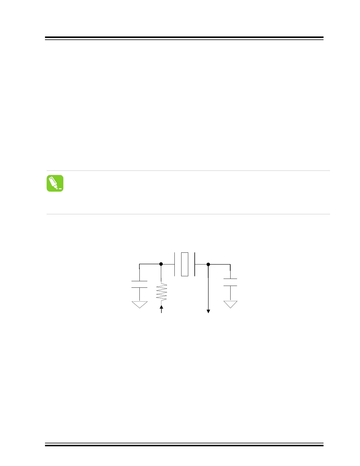
Figure 7-7. PIC32MZ/PIC32MM/PIC32MK/PIC32C and SAM T
ypical Primary Oscillator Crystal Circuit
X
OUT
X
IN
C1
C2
RS
XTAL
OSC2
OSC1
RG= 1M
C1
C2
XTAL
Note: Crystal R
S
is not required if using Automatic Gain Control or if X
OUT
and X
IN
are not clipping. T
o monitor X
OUT
or X
IN
on a scope, the user must use a special FET probe with ≤ 2 pF for good results. A standard Oscilloscope
10-12 pF probe will load and attenuate the crystal giving inaccurate results.
MCU Start-up Problems
©
2022 Microchip Technology Inc.
and its subsidiaries
Manual
DS70005439B-page 20