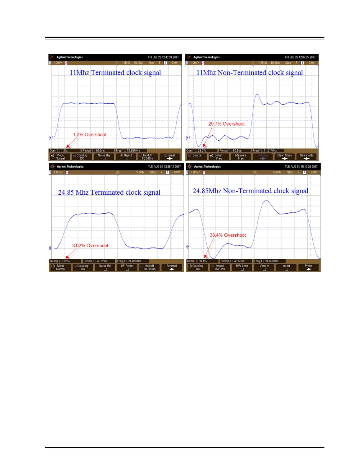
Figure 11-1. Signal Integrity Illustration of Before and After Transmission
11.1.1 Abbreviated General High-Speed Signal Layout Guidelines
1. Layout differential and high-speed traces first maintain differential impedance matching when required on PCB
layer 1 adjacent to ground plane layer on the same side of the PCB as the signal source/destination for MCU
devices.
2.
Ensure clock and high-speed signal traces have unbroken reference ground plane with no gaps or voids
beneath them.
3. Copper pour all voids on signal layers with signal ground.
4. Minimize the use of vias throughout the design on high speed signals. Vias add capacitance, impedance
changes, and frequency to signal traces which leads to reflections and radiated EMI.
5. Use the 3-Width rule to provide enough trace separation to avoid cross talk problems.
Note: See Complete PCB Layout Guidelines in the back of this document.
11.1.2 PIC32MZ/PIC32MK
In lieu of using termination resistors for MCU high-speed signals, some device families, such as the PIC32MZ,
PIC32MK have I/O output pin slew rate control features. By attenuating the rise and fall times you can improve signal
integrity and eliminate data transceiver errors.
Return to Checklist
Serial Data Corruption Errors
© 2022 Microchip T
echnology Inc.
and its subsidiaries
Manual
DS70005439B-page 34