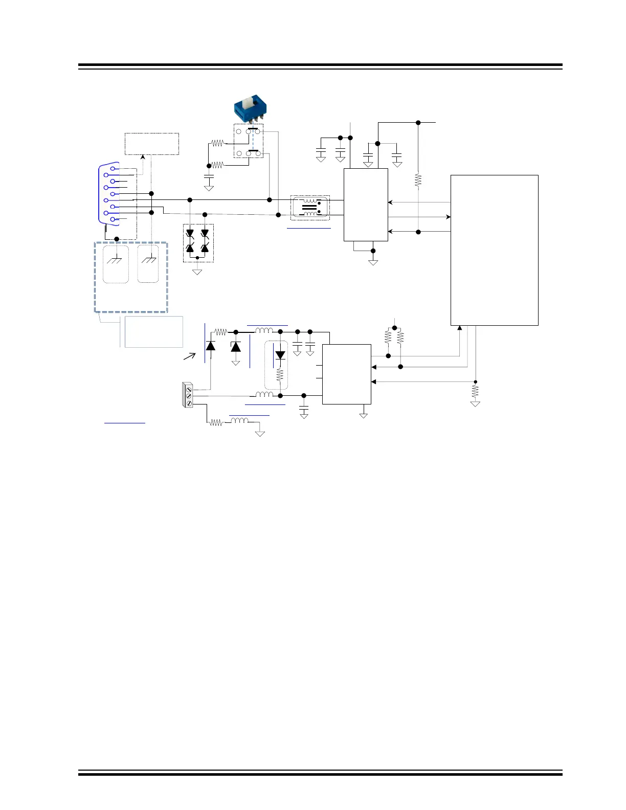
CAN-FD / LIN Bus Protection Circuit Example
NC
Common mode choke
8
3
Isolated
DC/DC Converter
CAN_FD
3.3v
WAKE
RxD
TxD
LBUS
CS
VREN
VBB
BAV19-TR
VSS
TPSMA6L48A
ACGRA4002-HF
1uf
0.1uf
MI0805J102R-10
50 1/2w
1K
220pf
VBAT+
NC
NC
3
2
1
LBUS
GND
Host Node Only
LIN
2
1
3
4
5
6
7
8
NOTE:
All LIN circuit
capacitors
50v or 100v
↓EMI / EFT Filters
MCHP2003B
Diode surge current rating
must be ≥ TVS I
PP spec
5 Ω
1/4W
MI0805J102R-10
MI0805J102R-10
10k
10k
10k
NOTE:
See appropriate MCU power
bypassing circuit configuration
illustrations in section 2.2
1k ohms @ 100Mhz DC=0.15Ω, 1A
NOTE:
MI0805J102R-10
5
9
4
7
2
6
1
NC
SHIELD
0.1uf
VIO
0.01uf
MCU
CxTX - CAN_TX
CxRX - CAN_RX
MCP2542FD
CAN_H
CAN_L
TxD
RxD
4700pf 50v
1
2
4
6
7
3.3v
5
VCC (5.0v)
3
10k
I/O
STBY
0.01uf
0.1uf
PAD
1
3
2
CDSOT23-T24CAN
NOTE:
Ground connection on all TVS MUST
be directly connected to ground plane
and not through a trace to ground to minimize inductance. In
addition, they should be located as close to the external DB9 and LIN
Connector as possible
Transient Suppressors
8 Mbit/s
8
UxRX
UxTX
I/O
60
60
CAN Termination
Enable / Disable
SWITCH
Signal naming:
PIC32MX/MM/MZ/MK - SAM/PIC32C
NC
DB9
Conn
Chassis
Gnd
IfDouble
Shielded
CANCable
Chassis
Gnd
IfSingle
Shielded
CANCable
Connect at only
one point in the
network else do not
connect
Optional Power
7- to -13v
PN#: ROE-1205S
PN#:OKR‐T/1.5‐W12‐C
SRF2012A-121YA
echnology Inc.