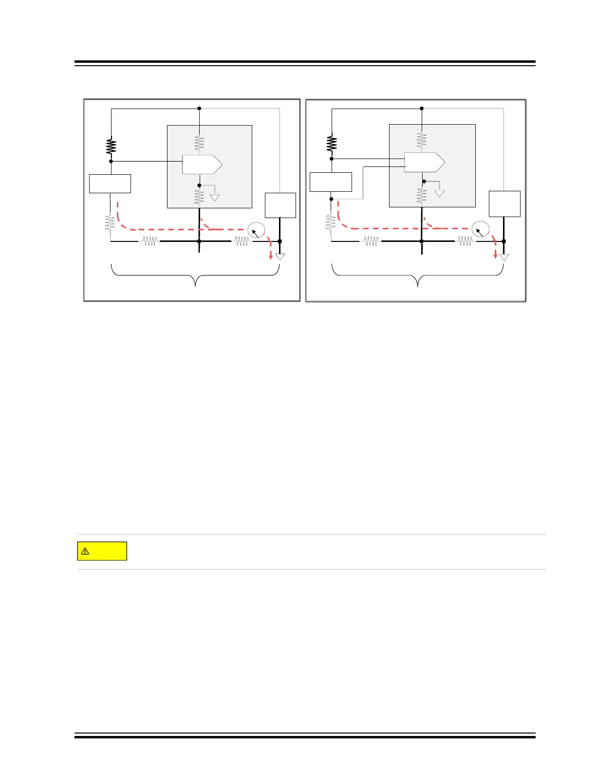
Figure 12-3. ADC PCB Design Induced Errors, Single Ended Versus Differential Diagram
R
GND
=DistributedresistancealonggroundplaneandconnectingtracesorwirestoloadSensor.
R
INT
=InternalMCUresistanceofmetalrunsandbondwirestoanalogpower&groundpins
ADC
INTGND
=LocalrelativegroundoftheinternalADCmodule.
ADC
MCU
LDO
GNDANA
Sensor
R
GND
R
GND
GROUNDPLANE
R
GND
10k
VDDANA / VDDIO
R
INT
R
INT
ADC
INTGND
V
OUT
AIN0
ADC SINGLE ENDED MODE
ADC
MCU
LDO
GNDANA
Sensor
R
GND
R
GND
GROUNDPLANE
R
GND
10k
VDDANA / VDDIO
R
INT
R
INT
V
OUT
AIN0
AIN3
ADC
INTGND
ADC DIFFERENTIAL MODE
OTHERIC’ s
OTHERIC’ s
Amp
Amp
Notes:
1.
Referring to the ADC Single-Ended mode figure above, the voltage as seen across the SENSOR by the ADC
has an offset proportional to the ground current and ground resistance due to the ground IR drop (i.e., voltage
difference), between the common sensor and the ADCINTGND. It is the sum of VRINT + VRGND and typically
can induce an error of 30 mv to 50 mv or more. ADC single ended conversion results are relative to the analog
input signal and the ADC internal ground, ADCINTGND.
2. Be sure to load the ADCx BIASCOMP, BIASREFBUF, and BIASR2R values from the NVM Software
Calibration Area Mapping Register to ensure the ADC is configured for optimum performance.
3. When an application demands high resolution, consider using differential mode for improved accuracy. Unlike
Single-Ended mode that measures an input relative to the internal ADC ground, and subject to the ground IR
drops/offsets, differential mode measures the difference between two inputs irrespective of the ADC internal
and external ground. If the ADC is in Differential mode, as shown in figure above, the input impedance of the
ADC is very high, resulting in very little current flow into the analog input pins. In turn, the IR drop into the AINx
pins is insignificant and the ground IR drop in the system is irrelevant. This allows for a much more accurate
low-level signal sensor measurement.
Separate the analog and digital grounds and connect them only at the nearest point to the power source to
minimize the ground IR drops.
ADC
© 2022 Microchip T
echnology Inc.
and its subsidiaries
Manual
DS70005439B-page 55