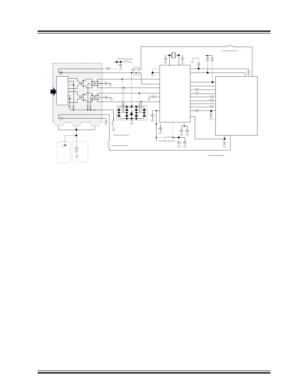
Figure 16-1. Ethernet RMII Design Example Diagram
ETHERNET RMII PROTECTION EXAMPLE
ARJC02-111008B
75
75
1000pf/2kv
75
75
0.1UF
1
RJ45 Shielded
Ethernet Port Conn
2
3
4
5
6
7
8
220
1
2
3
4
5
6
9
8
10
11
12
Green LED (Left)
Yellow LED (Right)
0.1UF
SHEILD
RJ45 10/100 Base-T
VDD
SHEILDSHEILD
1
NOTE
1. User must insure KSZ8081RN VDD minimum rise time ≥ 300us
2. KSZ8081RN RST# signal must be asserted low for ≥ 500us
3. After RST# de-assertion, user software must wait >100us before attempting to configure KSZ8081RN
NOTE:
Ground connection on all TVS MUST be directly connected to
ground plane and not through a trace to ground to minimize
inductance. In addition, they should be located as close to the
external RJ45 Connector as possible
MI0805J102R-10
1kΩ @ 100MHz, DCR=0.15Ω(max), 1A
Opt(B)
Chassis
(AC) Gnd
if available
(Preferred)
If chassis (AC) Gnd
not available
Opt(A)
10K
MI0805J102R-10
22UF
REXT
9
3
MCU
D5V0P4UR6SO
2
13
4
5
6
6.49k
1K
33
10K
1K
VDD
1
2.2UF
0.1UF
4
5
7
8
25Mhz ±50PPM
22pf
22pf
KSZ8081RNA
RXM
RXP
TXM
TXP
LED0 / ANEN_SPEED
X0
XI
1.2VCore
6
MDIO
MDC
RXD0
RXD1
REF_CLK
RST#
VDDIO
14
10
11
12
13
TXD0
TXD1
21
20
16
RXER
17
22
INTRP
PAD
Gnd
18
24
CRS_DV / PHYAD
15
10K
2
VDDA_3.3
22UF
0.1UF
0.1UF
VDD
TXEN
19
23
I/O
ETXEN – GTXEN
EMDIO - GMDIO
↑Transient
Suppressors
I/O
MI0805J102R-10
INT0 – EXTINT0
EMDC - GMDC
ERXD0 - GRX0
ERXD1- GRX1
ETXD0 - GTX0
ETXD1 – GTX1
ECRSDV - GRXDV
EREFCLK - GTXCK
ERXERR - GRXER
JP1
10K
(PIC32MX/MM/MZ - SAM/PIC32C)
33
33
33
33
33
33
I/O
220
CRS_DV
LED_PWR
LED_PWR
MI0805J102R-10
0.1UF
MI0805J102R-10
MI0805J102R-10
NOTE:
See appropriate MCU
power bypassing circuit
configuration illustrations
in section 2.2
16.1.5 Key Ethernet Protection Design Points
• The use of ferrites on the Ethernet PHY on the magnetics and the LED indicators in the PHY.
•
Ideally the Ethernet PHY shield must be connected to the chassis/earth ground if available. If the chassis/earth
ground is not available, then through a 10k resistor to logic ground. This is for ESD and ground loop isolation
from the MCU logic ground.
• Differential TX and RX pairs must be constructed as 100 Ohm, controlled impedance pairs from MCU to
ethernet controller, and ethernet controller to PHY. The signal distance between the components ≤ 2.5 inches.
Ethernet
© 2022 Microchip T
echnology Inc.
and its subsidiaries
Manual
DS70005439B-page 63