© Microhard Systems Inc. CONFIDENTIAL 28
IP9xx Series
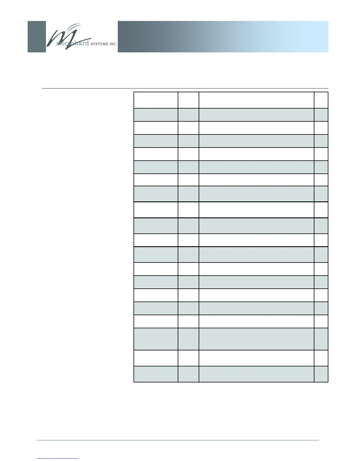
3.0 Hardware Features
Pin Name No. Description In/
Out
CAT1 33 Ethernet RJ45 Pin 1.
CAT4 34 Ethernet RJ45 Pin 4.
CAT2 35 Ethernet RJ45 Pin 2.
CAT3 36 Ethernet RJ45 Pin 3.
LINK LED 37 Ethernet LINK LED O
ACTIVITY LED 38 Ethernet Activity LED O
RXD0_485 39 Data Port. RS485 Receive Data Logic level
input into the modem.
I
RXD0_232 40 Data Port. RS232 Receive Data Logic level
input into the modem.
I
DE_485 41 Date Port. RS485 Driver Output Enable. Avtive
High Output.
O
!RSMODE 42 Sleep mode indication output. Active Low. O
!RE_485 43 Data Port. RS485 Receiver Output Enable.
Active low output.
O
!RESET 44 Active low input will reset module I
NC 45-46 *Reserved for future use.*
RSSI_LED3 47 Receive Signal Strength Indicator 3. O
RSSI_LED2 49 Receive Signal Strength Indicator 2. O
RSSI_LED1 51 Receive Signal Strength Indicator 1. O
SYS LED 48 This output indicates system status. Normal
Operation = Solid, Recovery = Fast Blink (3/s),
Loading/Upgrading = Slow Blink (1 every 2s)
O
TX LED 50 Output indicates module is transmitting data
over the RF channel.
O
RX LED 52 Output indicates receive and synchronization
status.
O
Table 3E: SIP921 Pin-Out Description (continued)