CARDIAC STIMULATOR
ENGLISH Page 23 of 49
1
1
0
0
USING THE MICROPACE CARDIAC
STIMULATORS
10.1 Connecting the Stimulus Connection Box
Connect the Stimulus Connection Box, MP3014 to the green PACE OUTPUT socket on the front panel
of the Stimulus Generator Unit. The EP Recording Equipment’s stimulus input cable(s) connect to this
connection box via shrouded 2mm connectors.
Do not connect any plug into the red EMERGENCY FIXED RATE PACING OUTPUT except in case of
Stimulus Generator Unit failure when emergency pacing is required.
Connect External ECG Inputs – Most modern EP Recording systems have only one high level ECG
output, connect this signal to the ECG1-INPUT with ECG cables provided (MP3034 or MP3109); you
will see this ECG from the EPS320 software as the ext-ecg1 accessed with the ALT-1 hotkey. You will
then have to select required ECG sensing source on the EP Recorder.
10.2 Switching on the system
Switch on the computer, the LCD screen and the Stimulus Generator Unit.
10.3 Using the computer
The Micropace Cardiac Stimulator system comes with a Bona Light System PC.
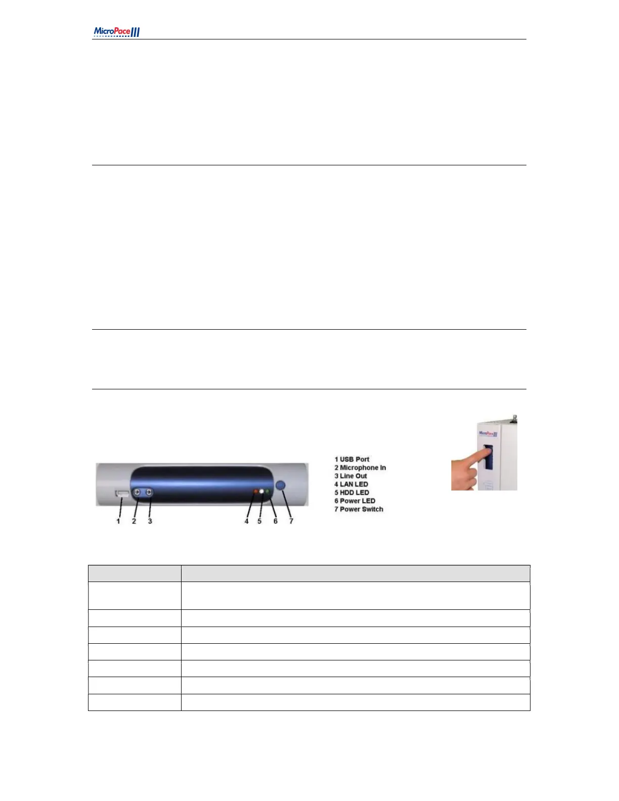
The front panel of the computer is shown in
Figure 8
Figure 8 Computer front panel for EPS320B/BT (left) and StimLab / StimCor (right)
FEATURE Explanation
1. USB Port:
For Micropace Configuration Management Tool only. Do not connect non-
Micropace USB devices.
2. Microphone In: Do not use.
3. Line Out: Connection for MP3113 touch screen audio Input. Use Line out on rear of PC.
4. LAN LED: Not Used
5. HDD LED: Not Used
6. Power LED: Indicates computer is switched on
7. Power Switch: Push On/Off
Table 5 Computer Front Panel Explanations