USER INSTRUCTION MANUAL
Page 44 of 49 ENGLISH
1
1
3
3
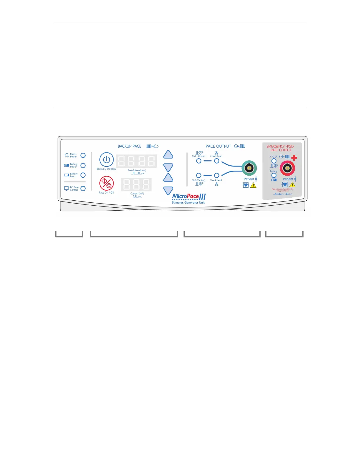
THE EPS320 STIMULUS GENERATOR UNIT
The Stimlab™ system uses the EPS320 Stimulus Generator Unit (SGU) for generation of cardiac
stimuli. The EPS320 has two independent opto-isolated stimulation channels.
13.1 EPS320 Stimulus Generator Unit layout
The front panel, shown in Figure 16 has four sections described below from left to right:
Figure 16 The EPS320 Stimulus Generator Unit front panel
Four power indicator lights on the extreme left:
(i) Mains Power (green/yellow)
GREEN ON - mains power is connected and unit switched On at the POWER switch,
backup battery is trickle changing, Stimulus Generator Unit is in PC CONTROL or
BACKUP MANUAL operation mode.
GREEN BLINKING- mains power is connected, unit in STANDBY mode; backup
battery charging.
YELLOW - Mains power available, but unit switched OFF; backup battery not
charging.
(ii) Battery Power (orange) - mains power lost, operating on backup battery. A minimum of 2
hours of operation is expected from a fully charged backup battery.
(iii) Battery Low (red) - battery charge low, only approximately 10 minutes of operation
remaining.
(iv) PC Pace Control (green) - Serial RS232 data link is functioning and Stimulator is under
control of computer.
POWER Backup Manual Normal Pace Output Emergency
LED’s Pace Green socket Pacing