USER INSTRUCTION MANUAL
Page 12 of 49 ENGLISH
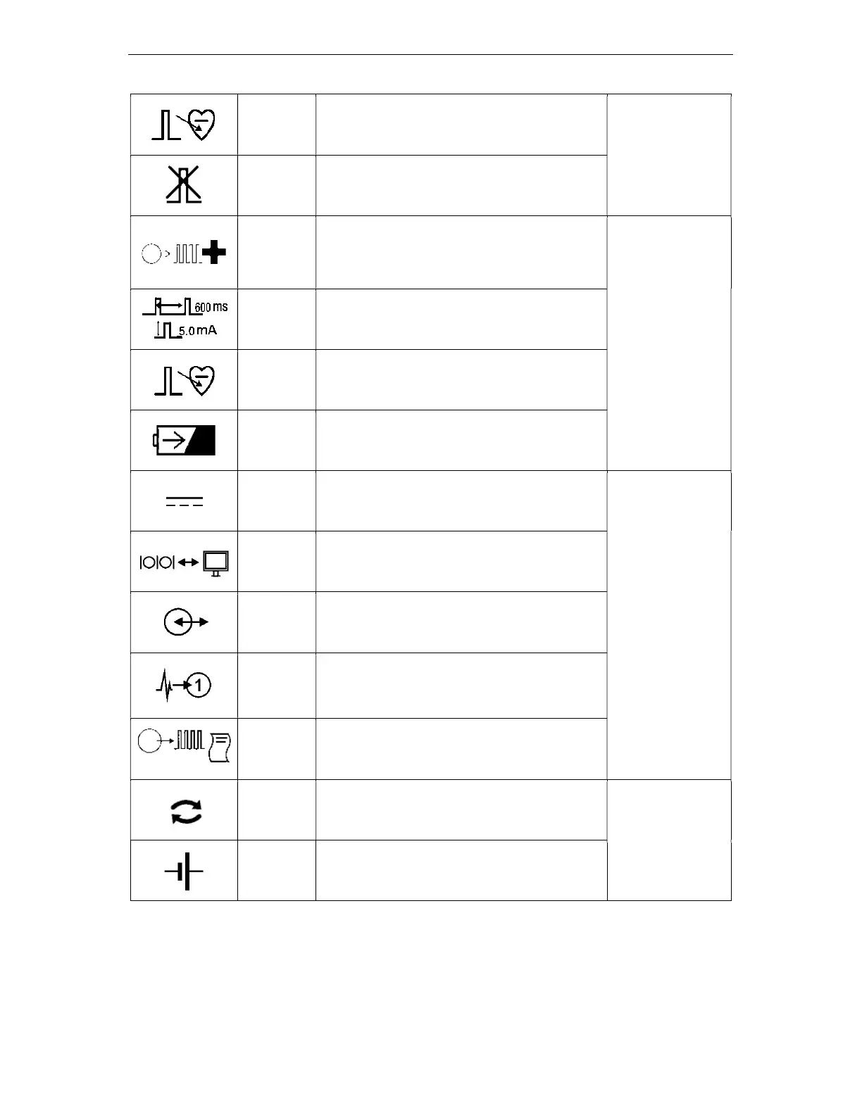
Ch2
(Ventic)
Green flash: Stimulus into Channel 2, usually
located in Ventricle.
Check
Lead
Stimulus current not able to be delivered
because of a break in the electrical lead /
circuit.
Emergenc
y Fixed
Pace
Output
Plug green patient connection cable into this
socket to immediately pace Ventricle Ch2 at
100ppm @ 5mA. Note: Ch1 Atrium is not
paced.
Right Front Panel
of Stimulus
Generator Unit
Pace V at
100ppm
@ 5mA
As above.
Pace V
Ch2
Green flash: Stimulus on Channel 2, usually
located in Ventricle.
Battery
Emergency Fixed Pace Output enabled and
powered from a battery with adequate charge.
DC Power
Direct Current power input, voltage and current
consumption as specified.
Rear panel of
Stimulus
Generator Unit
Computer
Link Port
Port for connection to controller computer, use
only Micropace supplied cables.
Auxiliary
Port
Port for connection to Stimulus Multiplexer
Box, use only Micropace supplied cables.
ECG-1
Input
ECG-2
Input
High Level ECG input, 1V peak-to-peak.
Sync-1
Output
Digital 0-5V sync output for triggering
recorders
Replace
Replace battery on specified date with
specified batteries.
Battery
Replacement
Label on SGU
Battery
Contains Batteries
Table 2 Explanation of symbols – specific to the SGU.