V6 VRF 50/60Hz
25
Part 2 - Components Layout and Refrigerant Circuits
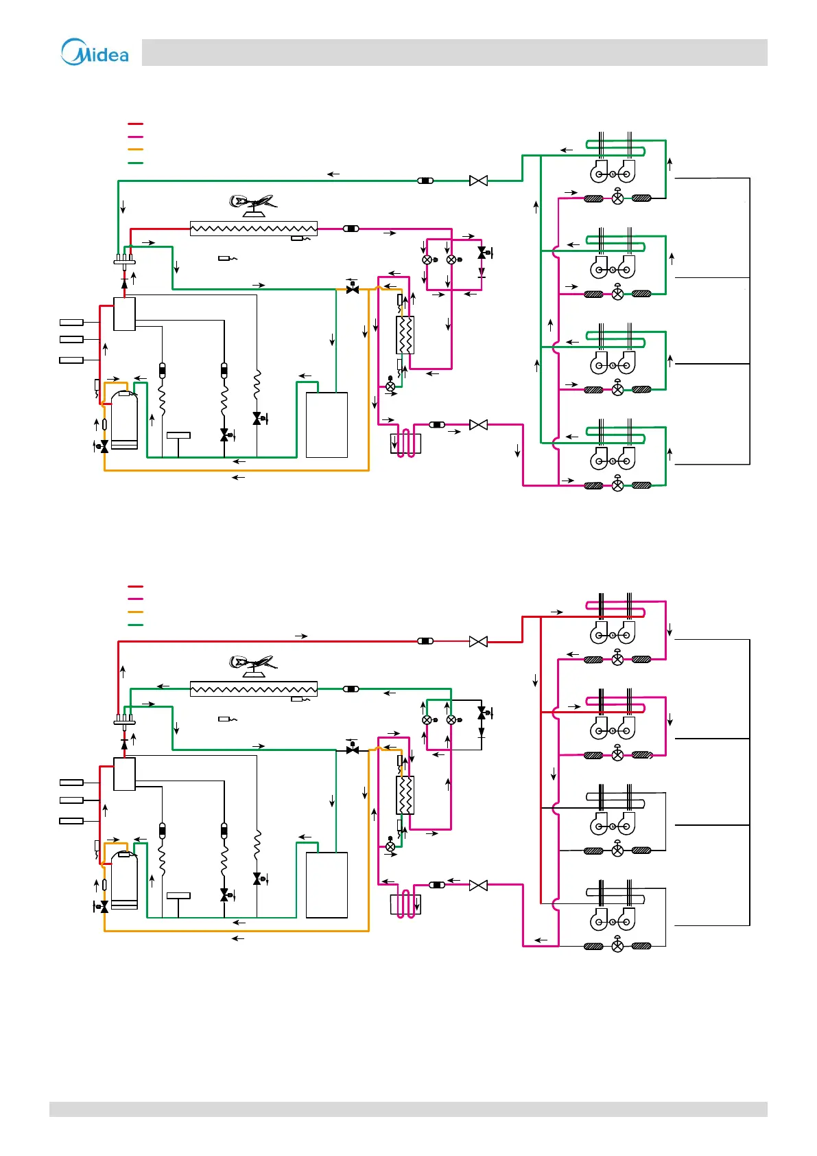
Oil return operation in heating mode and defrosting operation
Figure 2-3.7: 14/16HP refrigerant flow during oil return operation in heating mode and during defrosting operation
Heating operation
Figure 2-3.8: 14/16HP refrigerant flow during heating operation
SV7
EXVA
EXVB
8
8
SV6
7
1
15
12
9
3
2
4
5
6
11
10
14
13
High t
emper
a
tur
e, high pressure gas
High
t
empe
r
a
tu
r
e, high p
r
essur
e liquid
Medium
tempe
r
atu
re, medium pressure gas
L
ow
tempe
r
atu
re, l
ow p
ressure
EXVC
E
S
C
T3
T4
T6B
T7C1
T7C2
T6A
SV8A
SV4
SV5
480 st
eps
Fil
ter
Filter
480 steps
Unit on
Thermo
st
a
t off
Unit on
Thermost
at on
Unit on
Thermost
at on
Unit off
Fil
ter
Indoor unit ope
ra
tion
Fil
t
er
480 st
e
ps
Fil
t
er
Filter
480
st
ep
s
Filt
er
Filter
Fan
off
F
an
off
Fan
off
Fan
off
SV7
EXVA
EXVB
8
8
SV6
High temperature, high pressure gas
High temperature, high pressure liquid
Medium temperature, medium pressure gas
Low temperature, low pressure
7
1
15
12
9
3
2
4
5
6
11
10
14
13
EXVC
E
S
C
T3
T4
T6B
T7C1
T7C2
T6A
SV8A
SV4
SV5
Closed
Closed
Filter
Filter
Unit on
Thermostat off
Unit on
Thermostat on
Unit on
Thermostat on
Unit off
Filter
Indoor unit operation
Filter
Normal control
Normal control
Filter
Filter
Filter
Filter
Fan
on
Fan
off
Fan
on
Fan
on
16