Technical Information
7
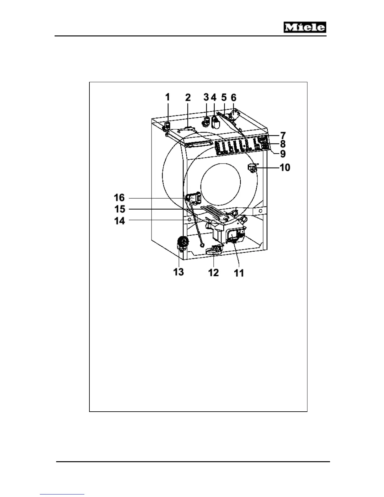
W1113, W1119, W1203, W1213 & W1215 Clothes Washers
1. (Y14) Inlet Valve - Cold
2. (M24) Motor - Water Path Control Unit
3. (Y12) Inlet Valve – Hot
4. (Z1) Interference Suppressor
5. (1n1) Control/Power Electronic
6. (K1/1) Heating Relay
7. (2n1) Control Panel/Display Module
8. (S2) Switch – On/Off
9. (S4) Switch – Door/Lid
10. Imbalance Sensor
11. (M5) Motor - Drum Drive
12. (B8) Float Switch
13. (M8) Drain Pump
14. (R30) NTC Temperature Sensor
15. (R1) Heater Element
16. (A2) Door Lock
D Layout of Electrical Components
Figure D-1: Layout of Components