OM-273473 Page 17
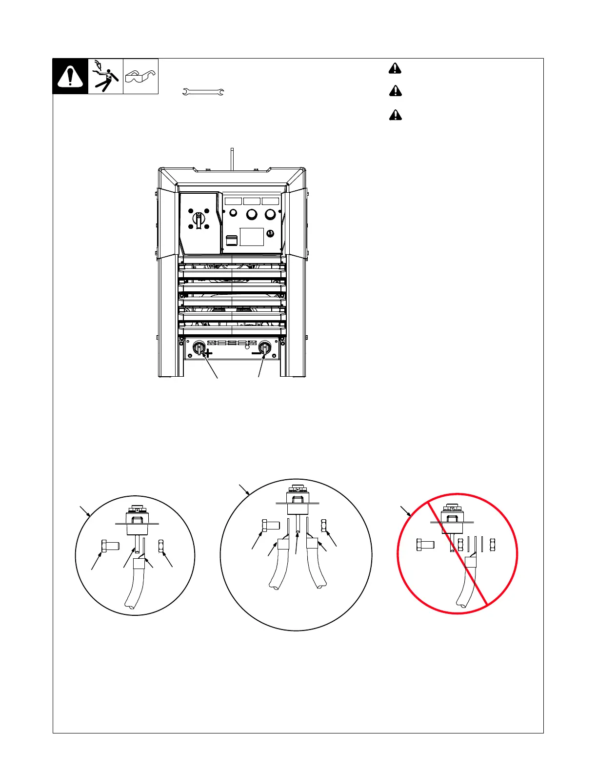
5-3. Connecting Weld Output Cables
XX
! Turn off power before connecting to
weld output tabs or receptacles.
! Do not use worn, damaged, under-
sized, or repaired cables.
! Failure to properly connect weld
cables may cause excessive heat
and start a fire, or damage your
machine.
Ensure all connections are tight.
Tab Connection
. Do not place anything between weld
cable terminal and output tab. Make
sure that the surfaces of the weld cable
terminal and output tab are clean.
1 Negative (−) Output Terminal
2 Positive (+) Output Terminal
3 Correct Weld Cable Connection For
Single Feeder
4 Correct Weld Cable Connection For
2/0 And Larger Double Cables
5 Incorrect Weld Cable Connection
6 Weld Output Terminal Bolt
7 Nut
8 Weld Cable Terminal
9 Output Terminal
Remove supplied nut and bolt from weld
output terminal. Insert bolt through hole in
weld cable terminal and hole in weld output
terminal. Screw nut onto bolt until weld
cable terminal is tight against output termi-
nal. Torque to 45-55 ft lb (61-75 N·m).
Tools Needed:
6
3
789
5
3/4 in. (19 mm) for output
terminal type connection
6
4
7
8
9
8
2/0 and larger double cables
2
Front View
1

 Loading...