OM-273473 Page 21
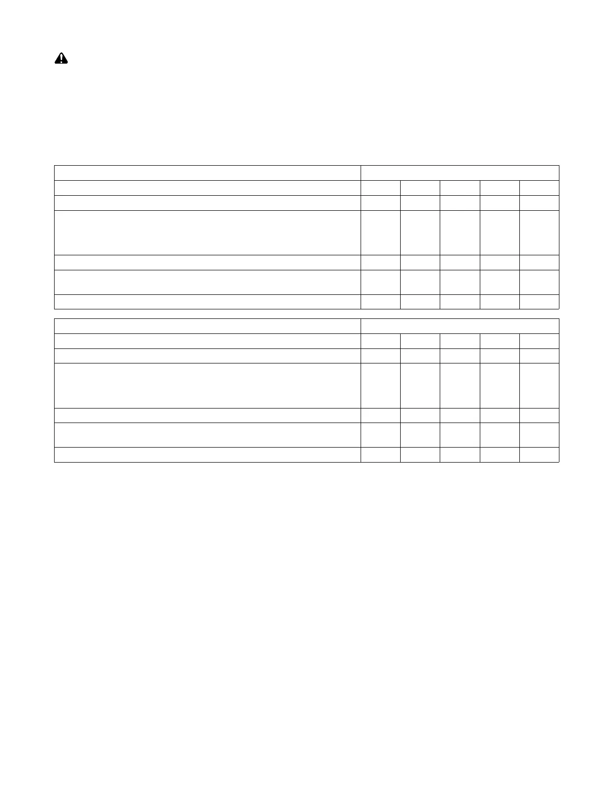
5-10. Electrical Service Guide
Elec Serv 2014−0
Failure to follow these electrical service guide recommendations could create an electric shock or fire hazard. These
recommendations are for a dedicated circuit sized for the rated output and duty cycle of the welding power source.
In dedicated circuit installations, the National Electrical Code (NEC) allows the receptacle or conductor rating to be less than the rating
of the circuit protection device. All components of the circuit must be physically compatible. See NEC articles 210.21, 630.11, and
630.12.
NOTICE − INCORRECT INPUT POWER can damage this welding power source. This welding power source requires a CONTINUOUS supply of
input power at rated frequency(+10%) and voltage (+10%). Phase to ground voltage shall not exceed +10% of rated input voltage. Do not use a genera-
tor with automatic idle device (that idles engine when no load is sensed) to supply input power to this welding power source.
. Actual input voltage should not exceed ± 10% of indicated required input voltage. If actual input voltage is outside of this range, output may not
be available.
350 Model 60 Hz Three Phase
Input Voltage (V) 230 380 400 460 575
Input Amperes (A) At Rated Output 34.1 20.4 19.2 16.7 13.3
Max Recommended Standard Fuse Rating In Amperes
1
Time-Delay Fuses
2
50 30 30 25 20
Normal Operating Fuses
3
70 40 35 30 25
Min Input Conductor Size In AWG
4
8 10 12 12 14
Max Recommended Input Conductor Length In Feet (Meters)
119
(36)
215
(66)
146
(44)
193
(59)
196
(60)
Min Grounding Conductor Size In AWG
4
8 10 12 12 14
500 Model 60 Hz Three Phase
Input Voltage (V) 230 380 400 460 575
Input Amperes (A) At Rated Output 58.7 34.9 33.2 28.9 23.3
Max Recommended Standard Fuse Rating In Amperes
1
Time-Delay Fuses
2
70 40 40 35 25
Normal Operating Fuses
3
90 50 50 45 35
Min Input Conductor Size In AWG
4
6 8 8 10 10
Max Recommended Input Conductor Length In Feet (Meters)
142
(43)
247
(75)
273
(83)
237
(72)
371
(113)
Min Grounding Conductor Size In AWG
4
8 10 10 10 10
Reference: 2014 National Electrical Code (NEC) (including article 630)
1 If a circuit breaker is used in place of a fuse, choose a circuit breaker with time-current curves comparable to the recommended fuse.
2 “Time-Delay” fuses are UL class “RK5” . See UL 248.
3 “Normal Operating” (general purpose - no intentional delay) fuses are UL class “K5” (up to and including 60 amps), and UL class “H” ( 65 amps and
above).
4 Conductor data in this section specifies conductor size (excluding flexible cord or cable) between the panelboard and the equipment per NEC Table
310.15(B)(16). If a flexible cord or cable is used, minimum conductor size may increase. See NEC Table 400.5(A) for flexible cord and cable
requirements.