TABLE OF CONTENTS
SECTION 1 − SAFETY PRECAUTIONS - READ BEFORE USING 1.................................
1-1. Symbol Usage 1.......................................................................
1-2. Arc Welding Hazards 1.................................................................
1-3. Additional Symbols For Installation, Operation, And Maintenance 3.............................
1-4. California Proposition 65 Warnings 4......................................................
1-5. Principal Safety Standards 4.............................................................
1-6. EMF Information 4.....................................................................
SECTION 2 − CONSIGNES DE SÉCURITÉ − LIRE AVANT UTILISATION 5...........................
2-1. Symboles utilisés 5.....................................................................
2-2. Dangers relatifs au soudage à l’arc 5......................................................
2-3. Dangers supplémentaires en relation avec l’installation, le fonctionnement et la maintenance 7.....
2-4. Proposition californienne 65 Avertissements 8..............................................
2-5. Principales normes de sécurité 8.........................................................
2-6. Informations relatives aux CEM 8.........................................................
SECTION 3 − DEFINITIONS 9..................................................................
3-1. Additional Safety Symbols And Definitions 9................................................
3-2. Miscellaneous Symbols And Definitions 11..................................................
SECTION 4 − SPECIFICATIONS 12..............................................................
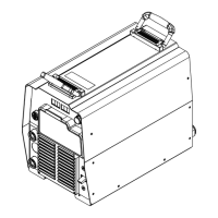
4-1. Serial Number And Rating Label Location 12................................................
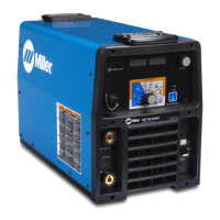
4-2. 350 Model Specifications 12..............................................................
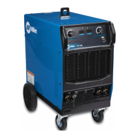
4-3. 500 Model Specifications 12..............................................................
4-4. Dimensions And Weight 13...............................................................
4-5. Environmental Specifications 13...........................................................
4-6. Static Characteristics 13.................................................................
4-7. Duty Cycle And Overheating 14...........................................................
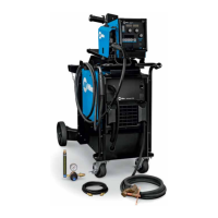
SECTION 5 − INSTALLATION 15................................................................
5-1. Selecting A Location 15..................................................................
5-2. Weld Output Terminals And Selecting Cable Sizes* 16........................................
5-3. Connecting Weld Output Cables 17........................................................
5-4. Remote 10 Wire Feeder Control Receptacle RC2 Information 18................................
5-5. Volt Sense Receptacle RC3 Information 18..................................................
5-6. Peripheral Receptacle RC22 Functions 19..................................................
5-7. Supplementary Protector CB1, Communication Panel, And E-Stop 19...........................
5-8. Aux Power And CB2 (Optional) 20.........................................................
5-9. Devicenet Receptacle 20.................................................................
5-10. Electrical Service Guide 21...............................................................
5-11. Connecting 3-Phase Input Power 22.......................................................
SECTION 6 − RECOMMENDED SETUP PROCEDURES 24.........................................
6-1. Welding Circuit 24.......................................................................
6-2. Arranging Welding Cables To Reduce Welding Circuit Inductance 25............................
6-3. Using Multiple Welding Power Sources 26..................................................
6-4. Voltage Sensing Lead And Work Cable Connections For Multiple Welding Arcs 27.................
6-5. Earth Grounding 30.....................................................................
6-6. 30 Points Of Mechanics In MIG Welding 32.................................................
6-7. Arc Blow 33............................................................................
6-8. Basic Welding Troubleshooting 34.........................................................
 Loading...