OM-273473 Page 19
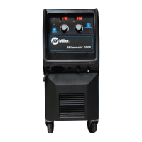
5-6. Peripheral Receptacle RC22 Functions
A
B
C
D
E
F
G
H
J
K
L
M
N
P
R
S
T
907 657-tp2
Socket Socket Information
A Output common
B Digital output 1 (DO1)
C Digital output 2 (DO2)
D Digital output 3 (DO3)
E Not Used
F Chassis ground
G Input common
H Request to turn on Touch Sense (DI1)
J Digital input 2 (DI2)
K Digital input 3 (DI3)
L Not Used
M Not Used
N Touched hardware signal
P Not Used
R Not Used
S Not Used
T Not Used
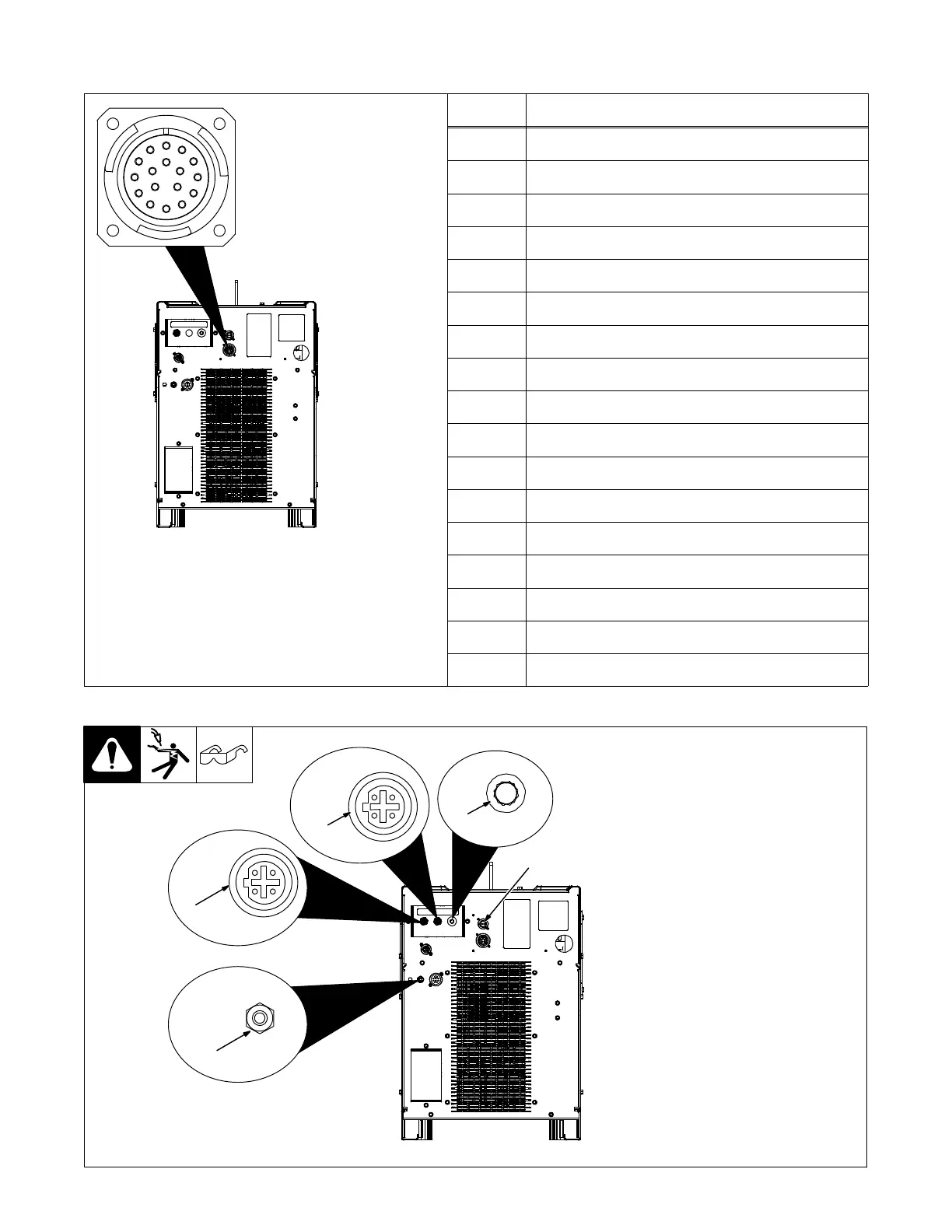
5-7. Supplementary Protector CB1, Communication Panel, And E-Stop
1 Ethernet Receptacle
Used for connecting a computer di-
rectly to the power source to ac-
cess configuration web pages.
2 Ethernet Receptacle
Used for connecting a robot directly
to the power source.
3 Supplementary Protector CB1
CB1 protects the wirefeed motor
from overload. If CB1 opens, the
wire feeder does not work.
. Press button to reset breaker. If
breaker continues to open,
contact a Factory Authorized
Service Agent.
4 Wireless (WiFi) Antenna
Antenna for connecting to the inter-
net via (WiFi) wireless connection if
selected during configuration.
5 E-Stop Receptacle RC24
A short across the two sockets al-
lows unit to weld.
3
1
4
2
5
907 657-tp2