OM-273473 Page 23
Input5 2013−04
! Installation must meet all National and
Local Codes − have only qualified per-
sons make this installation.
! Disconnect and lockout/tagout input
power before connecting input
conductors from unit. Follow estab-
lished procedures regarding the in-
stallation and removal of lockout/
tagout devices.
! Make input power connections to the
welding power source first.
! Always connect green or green/yellow
conductor to supply grounding
terminal first, and never to a line
terminal.
NOTICE − The Auto-Line circuitry in this unit
automatically adapts the power source to the
primary voltage being applied. Check input
voltage available at site. This unit can be con-
nected to any 3-phase input power between
230 and 575 VAC without removing cover to
relink the power source.
See rating label on unit and check input volt-
age available at site.
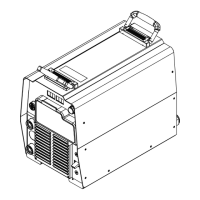
1 Input Power Conductors (Customer
Supplied Cord)
Select size and length of conductors using
Section 5-10. Conductors must comply with
national, state, and local electrical codes. If
applicable, use lugs of proper amperage
capacity and correct hole size.
Welding Power Source Input Power
Connections
2 Strain Relief Kit 274 563 Supplied With
Machine
Install strain relief of proper size for unit and
input conductors. Route conductors (cord)
through strain relief. Tighten strain relief.
3 Welding Power Source Grounding
Terminal
4 Green Or Green/Yellow Grounding
Conductor
Route green or green/yellow grounding con-
ductor through current transducer and con-
nect to welding power source grounding
terminal first..
5 Welding Power Source Line Terminals
6 Input Conductors L1, L2, L3
Connect input conductors L1, L2, and L3 to
welding power source line terminals.
Reinstall top cover on welding power source.
Disconnect Device Input Power
Connections
7 Disconnect Device (switch shown in the
OFF position)
8 Disconnect Device Grounding Terminal
9 Disconnect Device Line Terminals
Connect green or green/yellow grounding
conductor to disconnect device grounding ter-
minal first.
Connect input conductors L1, L2, and L3 to
disconnect device line terminals.
10 Over-Current Protection
Select type and size of over-current protec-
tion using Section 5-10 (fused disconnect
switch shown).
Close and secure door on disconnect device.
Follow established lockout/tagout procedures
to put unit in service.
5-11. Connecting 3-Phase Input Power (Continued)
Work like a Pro!
Pros weld and cut
safely. Read the
safety rules at
the beginning
of this manual.