OM-245 849 Page 10
4-3. Weld Output Terminals And Selecting Cable Sizes*
NOTICE − The Total Cable Length in Weld Circuit (see table below) is the combined length of both weld cables. For example, if the power source is
30 m (100 ft) from the workpiece, the total cable length in the weld circuit is 60 m (2 cables x 30 m). Use the 60 m (200 ft) column to determine cable
size.
! Turn off power be
fore connecting to
weld output termi
nals.
! Do not use worn
damaged, under
sized, or poorly
spliced cables.
Weld Output
Terminals
Weld Cable Size** and Total Cable (Copper) Length in Weld Circuit
Not Exceeding***
30 m (100 ft) or Less
45 m
(150 ft)
60 m
(200 ft)
70 m
(250 ft)
90 m
(300 ft)
105 m
(350 ft)
120 m
(400 ft)
Welding
Amperes
10 − 60%
Duty
Cycle
mm
2
(AWG)
60 − 100%
Duty
Cycle
mm
2
(AWG)
10 − 100% Duty Cycle
mm
2
(AWG)
100 20 (4) 20 (4) 20 (4) 30 (3) 35 (2) 50 (1) 60 (1/0) 60 (1/0)
150 30 (3) 30 (3) 35 (2) 50 (1) 60 (1/0) 70 (2/0) 95 (3/0) 95 (3/0)
200 30 (3) 35 (2) 50 (1) 60 (1/0) 70 (2/0) 95 (3/0) 120 (4/0) 120 (4/0)
* This chart is a general guideline and may not suit all applications. If cable overheats, use next size larger cable.
**Weld cable size is based on either a 4 volts or less drop or a current density of at least 300 circular mils per ampere.
***For distances longer than those shown in this guide, call a factory applications representative. Milan Ref. S-0007-G 2009−08
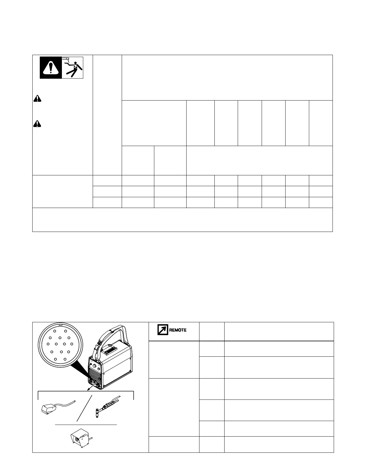
4-4. Remote 14 Receptacle Information
246 381-A
AJ
B
K
I
C
L
NH
D
M
G
E
F
14
Socket* Socket Information
A Contactor control 24 volts DC.
B Contact closure to A completes 24 volt DC
contactor control circuit and enables output.
REMOTE
OUTPUT
CONTROL
C Output to remote control; +10 volts DC output to
remote control.
D 0 to +10 volts DC input command signal from
remote control.
E Remote control circuit common.
CHASSIS
G Chassis common.