OM-245 849 Page 12
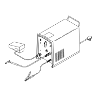
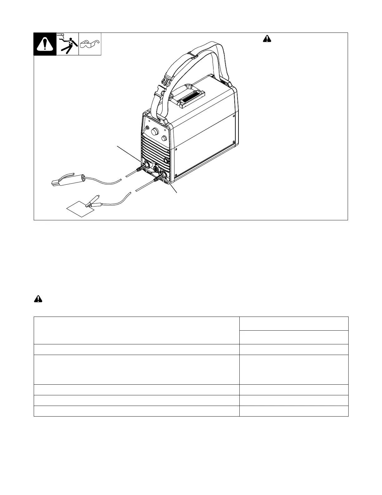
4-6. Stick DCEP (Direct Current Electrode Positive) Connections
! Turn off power before mak-
ing connections.
1 Negative (−) Weld Output
Terminal
Connect work lead to negative weld
output terminal.
2 Positive (+) Weld Output
Terminal
Connect electrode holder to posi-
tive weld output terminal.
3 Remote 14 Receptacle
If desired, connect remote control
to Remote 14 receptacle (see Sec-
tion 4-4).
2
1
4-7. Electrical Service Guide
. Actual input voltage cannot exceed -10% of minimum, or +10% of maximum input voltages indicated in table.
Failure to follow these electrical service guide recommendations could create an electric shock or fire hazard. These recommenda-
tions are for a dedicated branch circuit sized for the rated output and duty cycle of the welding power source.
Input Voltage (V)
Three-Phase, 40% Duty Cycle
380−440 +/− 10%
Input Amperes (A) At Rated Output 13.5−11.5
Max Recommended Standard Fuse Rating In Amperes
1
Time Delay Fuses
2
10
Normal Operating Fuses
3
20
Min Input Conductor Size In AWG
4
13 (2.63 mm
2
)
Max Recommended Input Conductor Length In Feet (Meters) (3.5)
Min Grounding Conductor Size In AWG
4
13 (2.63 mm
2
)
Reference: 2008 National Electrical Code (NEC) (including article 630)
1 If a circuit breaker is used in place of a fuse, choose a circuit breaker with time-current curves comparable to the recommended fuse.
2 “Time-Delay” fuses are UL class “RK5” . See UL 248.
3 “Normal Operating” (general purpose - no intentional delay) fuses are UL class “K5” (up to and including 60 amps), and UL class “H” ( 65 amps and
above).
4 Conductor data in this section specifies conductor size (excluding flexible cord or cable) between the panelboard and the equipment per NEC Table
310.16. If a flexible cord or cable is used, minimum conductor size may increase. See NEC Table 400.5(A) for flexible cord and cable requirements.