2 Get started
2-1 Electrical interface/Pin assignment
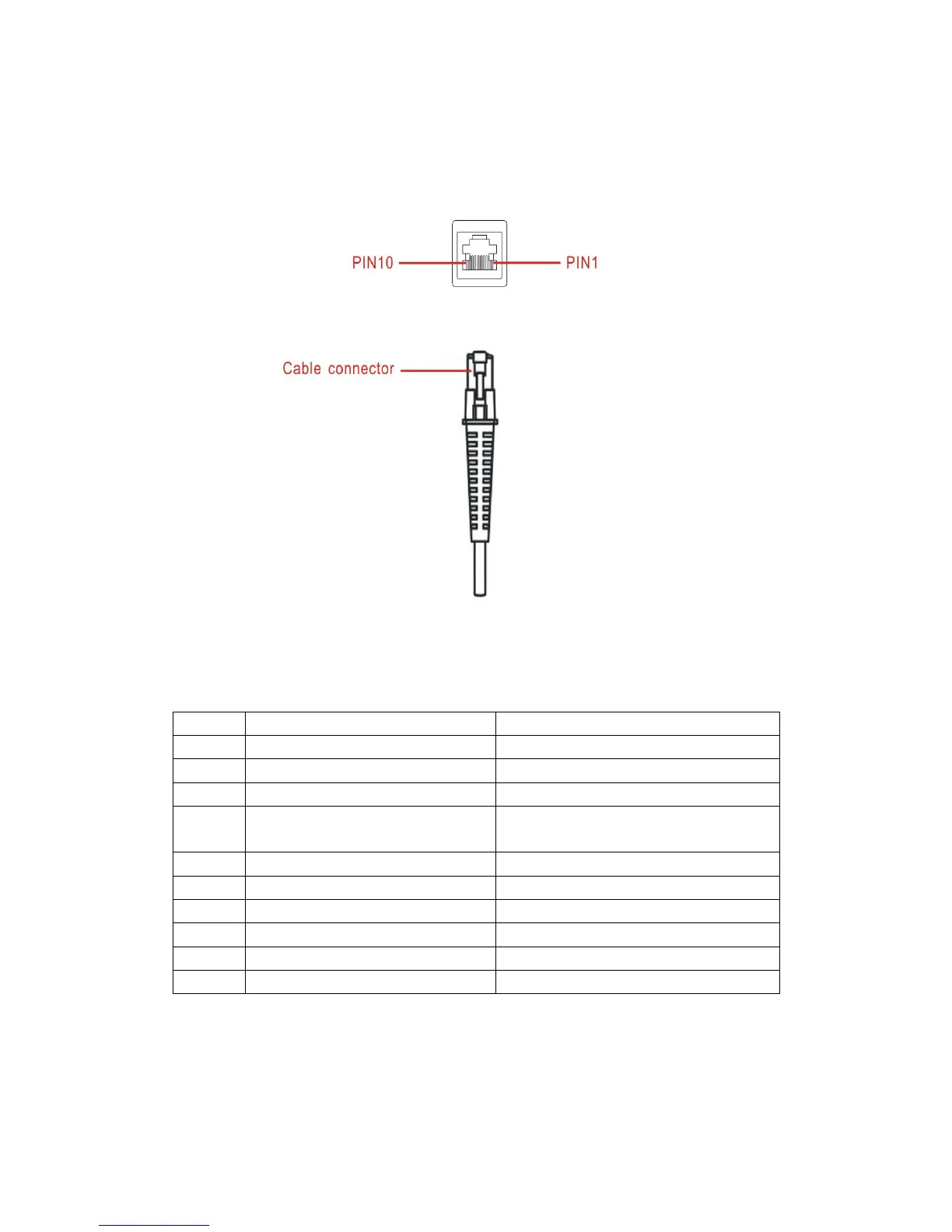
The scanner provides a RJ-45 cable connector.
Figure 2-1 Electrical interface/Pin
Table 2-1 lists the pin assignments of the scanner.
Table 2-1 Electrical interface/Pin assignment
(for interface auto selection purpose)
(for interface auto selection purpose)
Note: Voltage level of all RS232 Pin-outs (RXD, TXD, CTS and RTS) is 0V for logic low level and 3.3V
for logic high level. A transceiver (MAX232) PCB is designed inside the RS232 cable, and it can achieve
signal transition between TTL and RS232.