Optional Installation/Assembly 10-11
Figure 6A Figure 6B
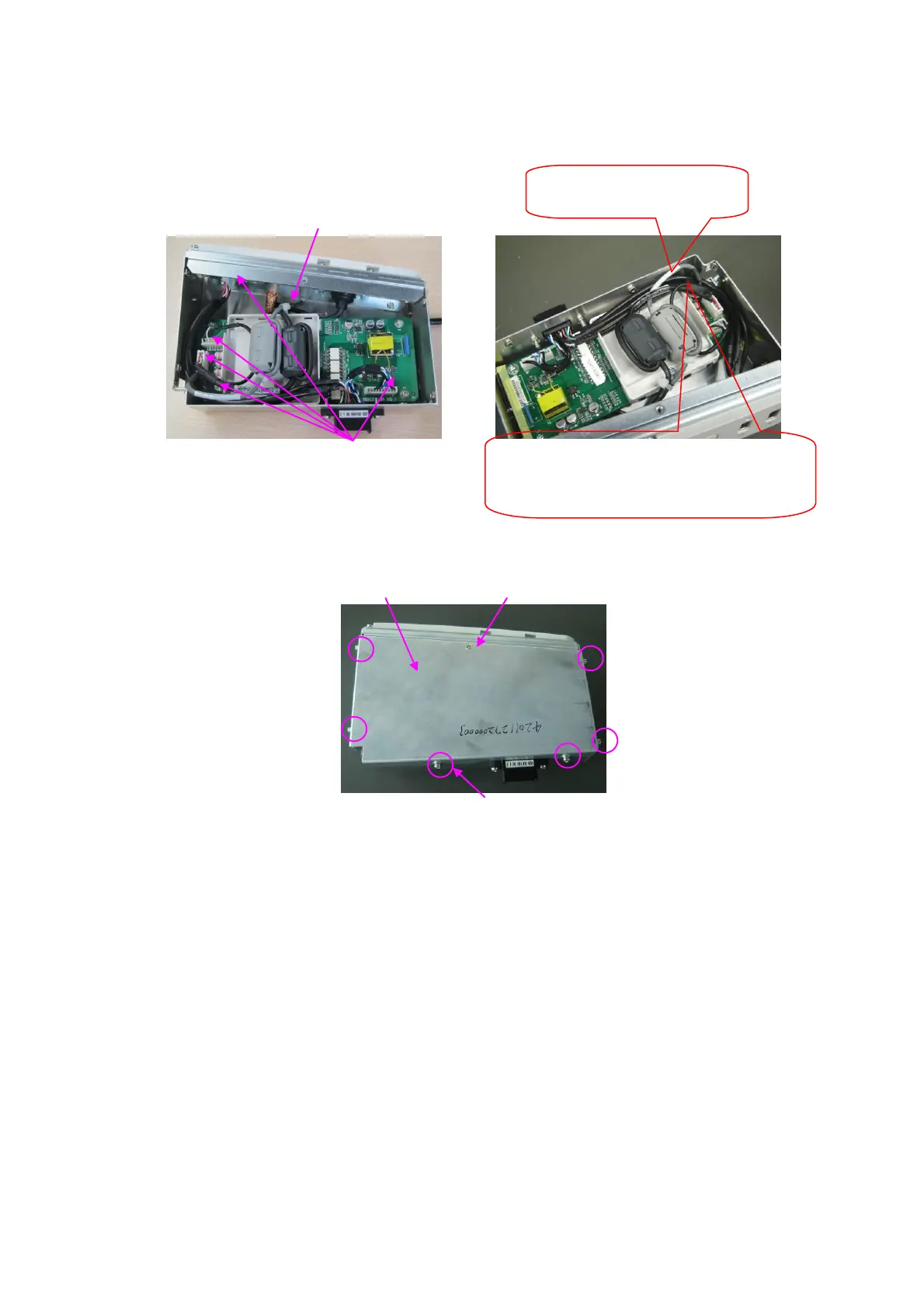
Make sure all outlets and connectors are securely
connected.
8. As shown in the following figure, use one M3X6 Philips sunk head screw and 6 pcs of M3X8
Philips pan headed screws to fix the ECG top cover and the assembly.
ECG top cover one M3X6 Philips sunk head screw
6pcs of M3X8 Philips pan headed screw
9. Confirm the connection from the back-end mother board to the ECG cable, and connect the
front board USB&ECG and pencil probe port assembly to the ECG cable connector (previous
front board USB assembly mounting location).And then use M4X8 Philips Pan headed screws
(3pcs) to mount it to the main unit rack, insert the pencil probe line to the outlet on the upper
left of the probe board, tidy the cables and use one cable tie 3X100 to fix the cables onto the
probe board cable-tie bridge (extra cables be left by the outlet )
 Loading...


