Function SPM Bit Description
center zero X36 = 1 Weight within ¼ d of zero
inside ZSR X37 = 1 Weight within zero-setting range
standstill X38 = 1 Standstill is active
out X39 = 1 Weight below zero or above Max
command error X48 = 1 For internal use only.
command busy X49 = 1 For internal use only.
power fail X50 = 1 Set after power-on (=power failure)
test active X56 = 1 Analog test was started.
cal active X57 = 1 For internal use only.
tare active X58 = 1 Instrument is tared.
marker bit 1 X64 = 1 Marker bit 1 set, after power-on the
markers are set to "0".
marker bit 2 X65 = 1 Marker bit 2 set, after power-on the
markers are set to "0".
marker bit 3 X66 = 1 Marker bit 3 set, after power-on the
markers are set to "0".
Example: [overload] function
SPM Bit [X34 = 1]
Function and output are active (e.g.: if 'overload' is reached, a lamp is lit).
SPM Bit [X34 = 0]
Function is active and output is not active (e.g.: if "overload" is reached, a lamp goes out).
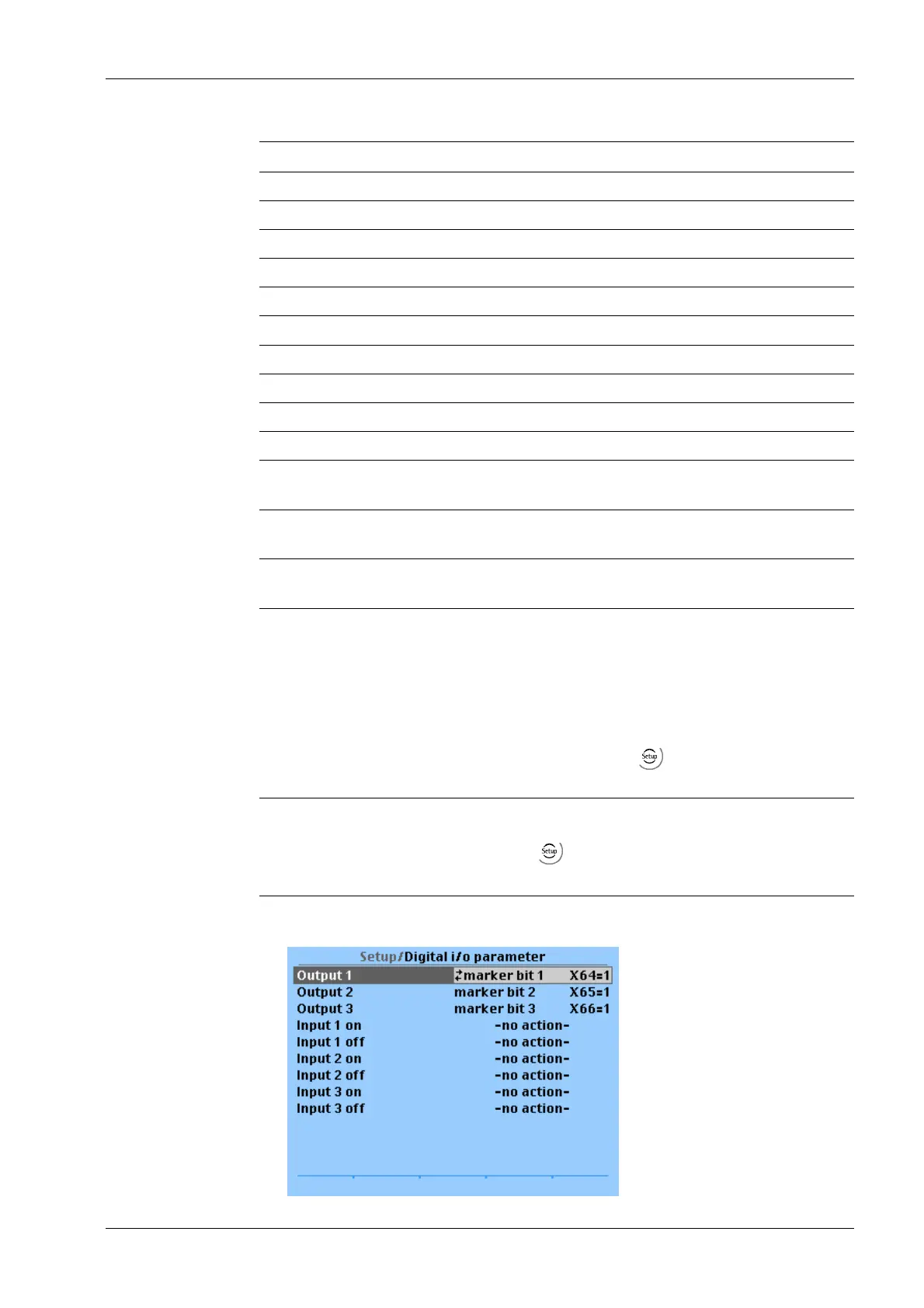
The parameters for the digital outputs are dened under -[Digital i/o parameter].
Note:
This menu item is only available if under -[Operating parameter]- [Application]
"Standard" has been selected.
Example:
7 Commissioning Transmitter Series PR 5220
EN-147 Minebea Intec
 Loading...