EasyManua.ls Logo

Minebea Intec PR 5230 User Manual

Minebea Intec PR 5230
303 pages
To Next Page IconTo Next Page
Page #1 background imageLoading...
Page #1 background image
Presented By
Dallas HoustonAustinFt Worth
NicolScales.com
800.225.8181
Contact Us
Nicol Scales & Measurement is an ISO Accredited Calibration
Company that has provided calibration, repair and sales of all types
of weighing and measurement products since 1931.

Table of Contents

Question and Answer IconNeed help?

Do you have a question about the Minebea Intec PR 5230 and is the answer not in the manual?

Minebea Intec PR 5230 Specifications

General IconGeneral
Housing materialStainless steel
Power Supply24 V DC
ApprovalOIML
Communication protocolsPROFIBUS DP, PROFINET, EtherNet/IP, Modbus RTU
Output SignalDigital
Process ConnectionNot applicable
Electrical ConnectionScrew terminals
Operating Temperature-10 °C to +50 °C

Summary

1 Introduction

1.5 This is what safety instructions look like

Explains the use of signal words (DANGER, WARNING, CAUTION) for hazard severity.

2 Safety information

2.1 General information

General safety regulations and product compliance information for safe operation.

2.4 Before operational startup

Instructions before starting the device, including visual inspection.

3 Device description

3.2 Overview of the device

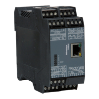
Details key features: accuracy, response time, display, housing, interfaces, and expansion options.

3.3 Housing

3.3.1 General information

Describes the stainless steel field housing, its IP66 rating, and mounting considerations.

3.4 Display and operating elements

3.4.3 Display

3.4.3.1 User interface

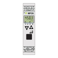
Describes the user interface, weight value display, and available weight units.

3.4.3.2 Device display

Details the device display capabilities, including 6-digit values and bar graph indication.

3.4.4 Operating elements

3.4.4.1 Keys on the device

Details the functions of the 3 accessible buttons for zero setting, taring, and test measurement.

3.4.4.5 Operation using VNC

3.5 Overview of connections

3.5.1 Plug-in cards

3.6 Device variants

3.6.1 Combinations for options

Lists combinations of accessories and their corresponding identifiers and descriptions.

4 Device installation

4.1 General information

Pre-installation checks and general procedures for connecting cables and power.

4.2.3 Cabling

4.2.4 Connecting a cable

4.3 EMC-compliant installation

4.4 Hardware construction

4.4.3 Weighing electronics board

Explains that the weighing electronics board plugs into the main board and lists available versions.

4.4.4 Network port

4.4.4.1 Ethernet port

Describes the Ethernet port's TCP/IP interface, transfer rates, and LED indicators.

4.4.5 RS-232 interface

4.4.5.1 Connecting the remote display PR 5110

Explains how to connect the PR 5110 remote display via the RS-232 interface.

4.4.5.2 Connecting a YDP14IS ticket printer

Details the connection and configuration for a YDP14IS ticket printer via RS-232.

4.4.5.3 Connecting an IS platform

4.4.6 RS-485 interface

4.4.6.1 Connecting to a PC or an RS-485/RS-232 converter

4.4.6.3 Connecting to PLC

4.4.6.5 Connecting the remote display PR 5110

4.4.6.8 Connecting an IS platform

4.4.6.9 Connecting digital load cells from type Pendeo®

4.4.7 Digital inputs

4.4.8 Digital outputs

4.4.8.1 Relay outputs

Details the three digital outputs with potential-free two-way contacts (relay outputs).

4.4.8.2 Opto-decoupled outputs

4.5 Connecting analog load cells and platforms

4.5.1 General information

Explains that analog load cells and platforms can be connected, with supply voltage protection.

4.5.2 Connecting a load cell with a 4-wire cable

Provides the terminal connections and port/color code for a 4-wire load cell.

4.5.3 Connecting a load cell with a 6-wire cable

4.5.4 Connecting 2-8 load cells (650 Ω) using a 6-wire connecting cable

4.5.7 External supply of the load cells

4.5.8 Connecting 2, 4 load cells via PR 5230/22 load cell junction board

4.5.8.1 Connecting load cells with a 4-wire cable

Shows the connection diagram and color coding for 4-wire load cells to the PR 5230/22 board.

4.5.8.2 Connecting load cells with a 6-wire cable

Shows the connection diagram and color coding for 6-wire load cells to the PR 5230/22 board.

4.5.9 Connecting an analog platform (series CAP…)

4.6.2 Analog outputs

4.6.3 Load cell junction board

4.6.5 ProfiBus-DP interface

4.6.6 InterBus-S interface

4.6.7 DeviceNet interface

4.6.8 CC-Link interface

4.6.9 ProfiNet I/O interface

4.6.10 EtherNet-IP interface

6 "EasyFill" application

7 Commissioning

7.1.3 Overwrite protection

7.2 Switching on the device

7.5 Finding and connecting a device with a notebook/PC

7.6 Finding and connecting the device automatically in the network

7.8 Resetting the network address

7.9 Operation using VNC

7.10 Operation via a web browser

7.11 System setup

7.11.1 Serial ports parameter

7.11.5 Fieldbus parameter

7.11.6 Network parameter

7.11.7 Weighing points

7.11.7.2 "xBPI scale" weighing point

7.11.7.3 "Pendeo® Truck/Process" weighing point

7.11.9 Limit parameter

7.15.9 Configuring digital inputs

7.15.10 Configuring digital outputs

7.15.12 Configuring analog output

7.16.5 Error log

7.16.5.2 Error log

9.1.4 Resetting the device to the factory settings

9.1.5 Updating new software with FlashIt

9.1.5.1 Updating in network with a DHCP service

Guides on updating software via a network connection with DHCP service enabled.

9.1.5.2 Updating via a point-to-point connection with DHCP service

9.1.5.3 Updating with a fixed IP address

10 ModBus protocol

12 Fieldbus interface

12.2 Scale protocol (8-Byte) for the "standard" application

12.2.3 Reading and writing data

12.2.4 Description of the I/O area (read/write window)

12.2.4.3 Reading and writing register via fieldbus

12.2.6 Fieldbus register

12.2.6.5 Register 4: Calibration information, error byte (read)

12.2.6.9 Register 8 15: Weight data (read)

12.2.6.10 Register 24 29: Limit values (read/write)

12.2.6.12 Register 80 89: State-controlled action bits (write)

12.2.6.13 Register 112 121: Transition-controlled action bits (write)

14 Repairs and maintenance

14.1 Repairs

Outlines the process for repairs, emphasizing contacting Minebea Intec service or dealers.

14.2 Maintenance

16 Error messages

16.1 Error messages measuring circuit

Lists error messages generated by the internal weighing electronics, their VNC text, causes, and remote display codes.

16.3 Error messages for xBPI scales

16.4 Error messages for Pendeo® load cells

16.5 Error messages during calibration

16.7 Error messages for Ex applications

16.8.2 Error in the "EasyFill" application

17 Specifications

Related product manuals