Description Data
Output current Max. 40 mA
Voltage drop 3.2 V @ I
max
Cables Screened
Connect cable screen (wire gauge max. 1.5 mm
2
) to the sleeve
of the cable gland.
Cable length max. 50 m
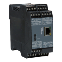
Component layout on the main board
In this option, jumpers R320R325 are not tted on the main board.
4.5 Connecting analog load cells and platforms
4.5.1 General information
Load cells or analog platforms (e.g. from the CAPP series) can be connected.
The supply voltage is protected against short circuit and overload.
Note:
The colors listed here are valid for the Minebea Intecload cells and connection cables of
type "PR "
Color code
bk = black
bu = blue
gn = green
gy = gray
rd = red
wh = white
ye = yellow
For additional information on the connection of load cells and junction boxes refer to
the corresponding installation manuals.
4.5.2 Connecting a load cell with a 4-wire cable
The following links between the terminal contacts are provided:
from Sense S+ to Supply V+
from Sense S- to Supply V-
Transmitter in eld housing PR 5230 4 Device installation
Minebea Intec EN-64