Do you have a question about the Minebea Intec MP 26 and is the answer not in the manual?
Provides an overview of the MP 26 transmitter's capabilities and design.
Lists key features and advantages of the MP 26 transmitter.
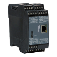
Details the physical dimensions, protection, and mounting of the device housing.
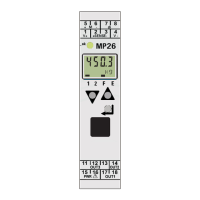
Explains the device's display elements and front panel controls.
Procedures for installing and removing the device from its mounting rail.
Instructions for connecting the power supply to the transmitter.
Guidance on connecting load cells to the MP 26 transmitter.
Details on connecting a digital input for control functions.
Instructions for connecting digital outputs OUT1 and OUT2.
Guidance on connecting the analog output OUT3.
Describes the device startup procedure and initial checks.
Explains the meaning of different LED color codes for device status.
Details the two display lines and their functions in different modes.
Overview of the three keys: Enter, Increment, and Decrement.
Outlines the different operating modes for configuration and parameter setting.
Introduces the calibration process and methods using device or tool.
Explains setting input and limit values and device parameters.
Steps to reset the transmitter to its default manufacturer settings.
Defines key terms and prerequisites for scale calibration.
Describes the two primary methods for device calibration.
Step-by-step guide for calibrating the device using its front keys.
Procedure to void residual weight and set the scale to zero.
How to set the tare function to measure net weight.
A practical example demonstrating calibration using specific values.
Configuration of filter time constant and bandwidth for signal processing.
Introduces output configuration for generating signals based on limits.
Details on setting limit values for outputs OUT.1 and OUT.2.
Configuration of the analog output (voltage or current) for OUT3.
How errors are identified on the display and general error handling.
A comprehensive list of error codes, causes, and possible remedies.
Specific types of sensor and wiring errors and their display indications.
Detailed specifications for the device's input signals.
Technical specifications for the relay and analog outputs.
Information on the electrical isolation provided by the device.
Specifications for the AC and universal power supply options.
Details on connecting to the controller via PC adapter and software.
Operating temperature, humidity, shock, and vibration limits.
General technical details including housing, terminals, safety, and mounting.
| Brand | Minebea Intec |
|---|---|
| Model | MP 26 |
| Category | Transmitter |
| Language | English |