MP 26 Transmitter Installation and Calibration Manual
Minebea Intec
3. Operation via Front Keys
3.1. Power ON
Switching ON the supply powers up the device, the device initializes itself (display, load cell
lines) and checks for any errors. The device status is indicated by the LED (red / green). For
proper operation, the system should be warmed up for minimum 20 minutes.
Initialization also takes place when loading the configuration through the serial port of the
MP26/10 software.
3.2. Status LED
The status LED indicates the status of the device. The status is indicated by the color of the
light:
Green indicates normal operation
Red indicates limit value1 is active/ON
Red blinking indicates instrument fault, configuration error
3.3. Display
There are two display lines available in the device. The first line displays the process values.
The second line displays the unit/error list /configuration settings / parameters.
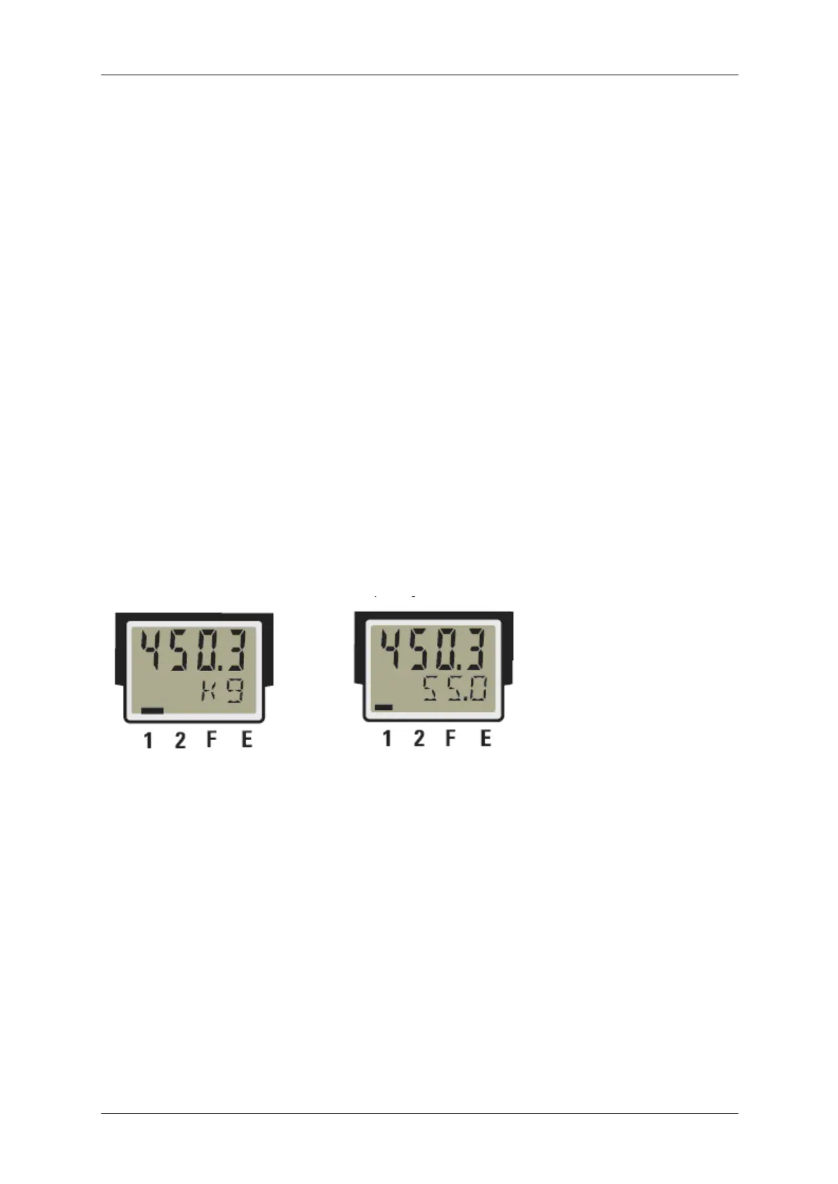
Default display mode Display of further operating levels
There are two modes of display available in the device based on the level in which the user is
working.
Default display mode: This shows the processed weight value along with its unit.
Operating mode: This mode is used to set the configuration or parameters or display error or
to calibrate the system
Note:
In case of incorrect input values, signals dependent on input (e.g. Inp1, Inp2, display value, Out3) will also
indicate FAIL.