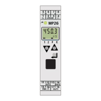
MP 26 Transmitter Installation and Calibration Manual
Minebea Intec
2. Installation
2.1. Connecting the Supply Voltage
Depending on the device version, connect the supply voltage as below:
MP 26/00 90…260 V AC ports: 15, 16
MP 26/01 24 V AC / DC ports: 15, 16
2.2. Connecting the Load Cell
The device can be connected to 4-wire or 6-wire
technology load cells. 6-wire technology load cells can be
connected directly as shown in figure.
If 4-wire technology is used:
short V + and S+
short V - and S-
Excitation voltage for bridge V+, V- ports: 1, 4
Excitation voltage measuring signal S+, S- ports: 2, 3
Bridge signal M+, M- ports: 5, 6
Measurement and data lines should be kept separate from control and power supply cables.
Sensor measuring cables should be twisted and screened, with the screening connected to
earth clamp.
2.3. Connecting Digital Input ‘di’
Input ‘di1’ is a digital input to the device which has to be connected as a
potential free contact. This di1 can be used for operation disabling, reset of
stored alarms and the min/max indicator to enable the tare function and zero
setting. It is configurable as a direct or inverse switch or push button.
Control input (as a potential free contact) ports: 7, 8
Switched voltage: 5 V
Current: 0.5 mA