MP 26 Transmitter Installation and Calibration Manual
Minebea Intec
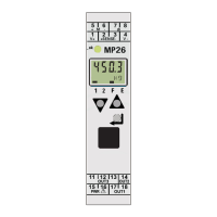
Increment Key: Is used to increment the values / slave pointer/ to display maximum value.
Enter Key: Is used to select extended operating level or error list, parameter, configurations
and installations levels.
LEDs: This LED indicates the status of the device. There are 3 color codings:
• green: limit value 1 OK
• red: limit value 1 active
• red blinking: instrument fault, configuration error
Digital OUT1: The bar displayed above 1 indicates the switching status of output OUT1 active.
Digital OUT2: The bar displayed above 2 indicates the switching status of output OUT2 active.
Decrement Key: Is used to decrement the values / slave pointer/ to display minimum value.
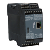
PC Connector: Slot for connecting the device to PC to ease work with the MP26/10 tool. To
facilitate withdrawal of the PC connector from the instrument, press the plug to the left.
Note:
The second LCD line normally shows the set point. When moving over to the parameter setting, configuration or
calibration level and at the extended operating level, the parameter name and value are displayed alternately.