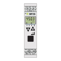
MP 26 Transmitter Installation and Calibration Manual
Minebea Intec
Overload
The device is able to generate an alarm signal on overload. For this signal to assert the limits,
the values should be entered suitably in terms of their physical weight values.
Generally, this is set as:
Alarm (Signal ON) = FSD (Max Load) + overload (Hysteresis)
Overload = 9*d
Display division (d) = max load / scale interval.
The scale interval may be 1 or 0.1 or 0.01 or 0.001 based on the decimal point set calibration.
Low Pass Filter and Bandwidth
A first order mathematical low pass filter with adjustable time constant and bandwidth is
built in.
The bandwidth is the adjustable tolerance around the measured value within which the filter
is active. Measurement value changes in excess of the adjusted bandwidth are not filtered.
This is set in b.F1.
The input signal display is delayed. The higher the value, the slower the display.
This is set in t.F1
4.2. Calibration
Calibration can be conducted in two ways: the easiest way is to use the MP26/10 tool and
download the settings to the device. The other way is to use the device. Calibration is
conducted as follows:
Initial Setting:
Phase 1: Disable tare and special linearization
Phase 2: Configure the initial settings relating to input and output.
Calibration
Calibration can be done in two ways
• Using front keys or
• The MP26/10 tool.
Each way contains two methods to calibrate the device
• Calibration by load
• Calibration by value

 Loading...